Tuesday, May 31, 2016

Section: 26
Hours: 6

I primed two batches of parts today. I did the first batch before lunch.

 I cleaned up the gun and had lunch and then shot the second batch.

By the time I finished the outside air temperature had reached 100! Shooting paint with the bunny suit, rubber gloves and mask on when it's this warm isn't much fun. The gloves filled with water (sweat) and I had to be careful to not dribble on the painted parts. It was very nice to get the gear off and rehydrate!

Monday, May 30, 2016

Section: 26
Hours: 9

Today I washed and acid etched the parts I've been prepping the last week. Whew! Tomorrow morning while it is still cool I'll get out the spray gun and prime the parts.

Sunday, May 29, 2016

Section: 26
Hours: 4

I continued prepping parts for the fuselage.

The outboard seat rib requires fluting to curve the rib to fit the contour of the fuselage. This is the first fluting I've done to add a curve instead of removing one :-)

Saturday, May 28, 2016

Section: 26
Hours: 6

I continued pulling parts and doing prep work. I used the die grinder with the small scotch brite disks to smooth out all the interior holes. There are just a lot of parts to get ready for prime paint next week.

Friday, May 27, 2016

Section: 25
Hours: 8

I riveted in nut plates to the spar carry through.

Then I pulled and prepped more bulkhead parts.

One of the counter sink holes was too close to the flange so I had to remove the counter sink cage and carefully do the counter sink using the drill press.

Here's another set of parts filed, polished, deburred, dimpled and counter sunk.

And some more parts. Lots of parts in the fuselage!

Tuesday, May 24, 2016

Section: 25
Hours: 5

I continued prepping parts. The spar carry through has a lot of holes that need to be counter sunk. Just like the wing spar but (thankfully) smaller.

Monday, May 23, 2016

Section: 25
Hours: 5

I spent some time unwrapping and sorting the cellophane wrapped bundles of parts. Then I started picking and prepping parts. Lots of filing, polishing, hole deburing and dimpling.

Woody got busy on removing the plastic protective covering.

Friday, May 20, 2016

Section: 25
Hours: 6

Today I uncrated and inventoried the fuselage kit. My shelves have been emptied of wing parts so now was a good time to tackle this project. The shelves are now filled with fuselage parts just waiting to be assembled...

Woody helped pull miles of paper packing out of the box. It will be nice not having the box sitting in the middle of the driveway anymore.

Here's the small hardware all neatly wrapped in bags and boxes. I've found it's best to keep all the hardware in the brown bags. When hardware is called out in the plans, I look up what bag it is in from the inventory list and then pull the bag and get the hardware. I store the bags in bins labeled with the bag number so I can easily find the bag I'm looking for. I made the mistake of emptying the bags for the empennage kit into a divided box and the parts got mixed up after an accidental fall to the floor. If you keep them in the brown bags that can't happen.

Wednesday, May 18, 2016

Section: 23
Hours: 4

I started work on the aileron actuation system. You cut the push rod tubing to length and then drill 6 equally spaced holes in both ends for riveting in the end connectors. I wrapped a piece of masking tape around the tube end with a little overlap. Then I cleanly sliced the tape and peeled it off and laid it out on a flat surface. I drew a line .25" from the end and divided it into 6 even spaces using my micrometer. Then I wrapped the tape back onto the tubing and center punched on the marks on the tape to layout the hole pattern for drilling. It helped to butt the tube up to a back board at 90 degrees and then align the tape parallel to the back board as you lay it on the tubing.

The threaded rod ends were slightly loose so I had to temporarily put a small length of electrical tape on the rod end and then jam it into the tube to hold it in place for drilling the first hole. After the first hole was drilled I was able to insert a cleco to hold the assembly in place.

Woody inspected the drilled tube ends.

Tuesday, May 17, 2016

Section: 20
Hours: 6

The adjustable set holder in my squeezer got bent somewhere in the last 5,000 rivets or maybe I screwed it too tight for dimpling operations. Anyway, I ordered a replacement from PlaneTools.com It arrived a couple days ago and I installed it in the squeezer today.

I riveted on the aileron and flap gap seals today. Midway out on the wing, the plans call out 2 AD3-4 length rivets where the skins overlap. I though they were too long. The AD3-3.5 length was perfect so that's what I used. The way the skins are cut, they don't actually overlap at the rear spar.

I was able to squeeze all of the rivets on both sides of the gap seals. The quality of the rivets with the new adjustable set holder was very good. It was much easier to get square heads when the set holder is true.

The plans are not entirely clear about the orientation of the stiffener at the end of the flap gap seal. I placed them with the angle flange inside so the nut plate in the skin is visible. (Sorry for the shadowy picture).

After I got the gap seals in place, I installed the ailerons using the hardware called out in the plans. It's a little difficult installing the washers so I cut a semi circle into the edge of a thin stick that I placed the washer in and then slid the stick between the mating pieces to align the washer with the bolt hole.

Monday, May 16, 2016

Section: 20
Hours: 6

I spent this morning reviewing the wing wiring. I'm planning on using LED navigation, strobe, landing and taxi lights. The AeroLED nav/strobe lights look like they are a nice solution. I visited their web site to see how to wire them up. They recommend using a 20ga 3 wire shielded cable to prevent radio interference / noise when you have the strobe running. Particularly if you are going to be using a Garmin radio stack (which I'm planning on). The wiring bundle supplied with the kit has the 20 ga wires required, but not in a shielded bundle. I spent the rest of the morning researching this and didn't come to any conclusion. I would like to use the provided wiring harness, but I really don't want to have to chase down radio interference problems.

I'd like to settle the wiring issues now because it is easy to route the wires while the bottom panels are off. However, lots of builders recommend to build on and worry about the wiring later.

After lunch I washed, acid etched and primed the aileron and flap gap seals and some small parts for the ADAHRS mount.

My plan is to attach the gap seals and then work on mounting the ailerons and flaps and build the control rod assemblies while continuing to research the wiring. I'll leave attaching the bottom skins until later in the project when I have a better idea about the wiring.

Saturday, May 14, 2016

Section: 18
Hours: 2

The balloon on the pressurized tank stayed inflated overnight!!!

 I feel confident the tank doesn't have leaks at this point so I bolted and screwed it onto the spar! I had  a problem getting one of the bolts started on the right tank. Today I was extra careful to finger tighten each bolt to make sure it was fully engaged with the first thread of the nut plate before I put the wrench to it. I successfully got all the bolts torqued (42 in#) and marked.

Section: 20
Hours: 4

I finished off the day prepping and dimpling the bottom wing skins.

Friday, May 13, 2016

Section: 18
Hours: 1

The green balloon didn't stay inflated overnight. I pumped the tank up again and spayed soapy water around looking for the leak. All I could find was a leak at the balloon. Here's the bubbles around the balloon neck.

I had tried tie wraps and electrical tape to secure the balloon to no avail. I also tried looping some wire around the electrical tape and twisting it to clamp it down but that leaked also. Finally I thought to use some rubber strand (FAI contest rubber for indoor model airplanes) looped, stretched and tied off at the end of the balloon. Rubber from a rubber band would probably also work. I pumped up the tank around noon and the balloon is still inflated this evening. All my tank leaks so far have been at the threaded fittings, the gas cap or the test apparatus. I've been a little anal about pursuing this, but I really don't want to chase down gas leaks after the tanks are installed. Much easier to address any leaks while I have full access to the tank. Hopefully tomorrow morning the balloon will still be inflated.

Section: 20
Hours: 4

I started work on the bottom skins. It looks like they are going to fit very nicely with a very small gap to the leading edge skins.

I finished up the edges and final drilled the holes for the 6 access panels and started work on the ADAHRS mounting plate. I'm not sure if I'll be actually putting my ADAHRS on this plate- I think the Garmin ADAHRS can be mounted on the panel in the cockpit. I'm going to install the plate anyway to fill the holes in the bottom skin and maybe it will be useful for some other purpose later on.

Thursday, May 12, 2016

Section: 18
Hours: 6

After a couple false starts over the last couple days I successfully pressure tested my tanks. Initially I had a major leak at the air valve and hose assembly used for pumping air into the right tank. After tightening down the hose clamps I was able to get the balloon to inflate and stay inflated. I sprayed down all the seams and rivets on the tank with soapy water and was not able to see any leaks. The balloon held for 5 hours until a humming bird flew up to it and popped it!

I got in a rush and immediately started testing the left tank without any success. Then I remembered I hadn't applied thread sealant or torqued down the drain sump, fuel strainer or the return line plug. I took care of that and pumped up the tank only to remember I hadn't taped over the gas cap. It took me 2 tries to get the gas cap sealed up with tape. The green balloon is now staying inflated. I'll check it again in the morning. Hopefully the humming bird won't be attracted to a green balloon.

Between testing the tanks, I did the prep work on the aileron and flap gap seal pieces. Van's just issued a SB for cracking around the inboard aileron support bracket. I've already riveted everything in place and the SB advises not redoing it unless a crack later developes. I did trim the corner of the aileron gap seal per the SB to make inspection easier.

I spent a large part of the afternoon attaching the right tank to the wing. Lots of bolts and screws. I found the drag friction on the z-flange attach point AN3 bolts was about 18 in# so I torqued them to the recommended 20-25 in# plus the 18 in# of drag for a total of 43 in#.


Wednesday, May 11, 2016

Section: 17
Hours: 7

Richard came over and we riveted the top edge of the outboard left and right leading edge sections to the spar.

After Richard left, I riveted the bottom edges which were easily accessible.


After riveting the edge to the spar, I riveted the inboard rib flange to the spar using solid rivets. I wanted to put the manufactured head on the rib flange so I had to use the bent stick on the rivet gun due to the tight fit.

Here are the manufactured heads after driving them.

Here's the shop heads.  

Here's what the wing will look like at the top of a loop :-)

Tuesday, May 10, 2016

Section: 17
Hours: 7

I will be installing an AOA / pitot tube with an AOA display in the cockpit so I've been debating whether I should also install the stall warning vane. It is easiest to install before you attach the leading edge to the spar. I had already cut out the slot for the vane so if I leave out the stall warning vane I would have to somehow fill in the slot. I decided that it would be good backup to have the stall warning vane incase the fancy glass panel goes black at some point.

So, I rounded up all the components and assembled the stall warning vane with lots of washers from several different bags of parts. When I went to install the vane in the leading edge assembly I discovered that I had installed the wrong outboard ribs. I mistakenly had put the W-1008-L rib in the left leading edge and the W-1008-R rib in the right leading edge. This is completely backwards- the right rib goes in the left leading edge and the left rib in the right. Silly me!

I drilled out all the rivets and swapped the outboard ribs to the correct assemblies and then riveted them back in. I drilled out all the rivets very carefully today, but a couple in the nose area were a little hard to extract. Many months ago I had ordered an oops rivet kit from Avery - before they closed their doors :-( I finally got to use a couple to complete the job today.

Here is the stall warning vane assembly installed on the corrected inboard rib.

Next I attached the outboard leading edge pieces to the spar. I installed all the pull rivets in both wings.

Here are the wings nestled in the cradle for the night. Richard and I will rivet the leading edge skins to the spar flange tomorrow and then I'll move on to work on leak testing and installing the tanks.

Monday, May 9, 2016

Section: 13
Hours: 2

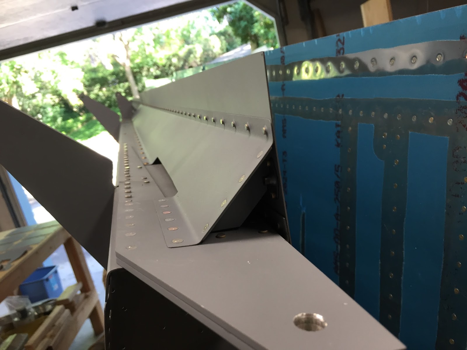
Today I double checked my work and reread the construction manual in preparation for joining the leading edge pieces to the spar. When I trial fitted the outboard leading edge assemblies, I noticed I had overlooked breaking the joining edges. Since the holes were already dimpled, I couldn't use my edge break roller. I manually used my duck bills and put a slight break along all the edges.

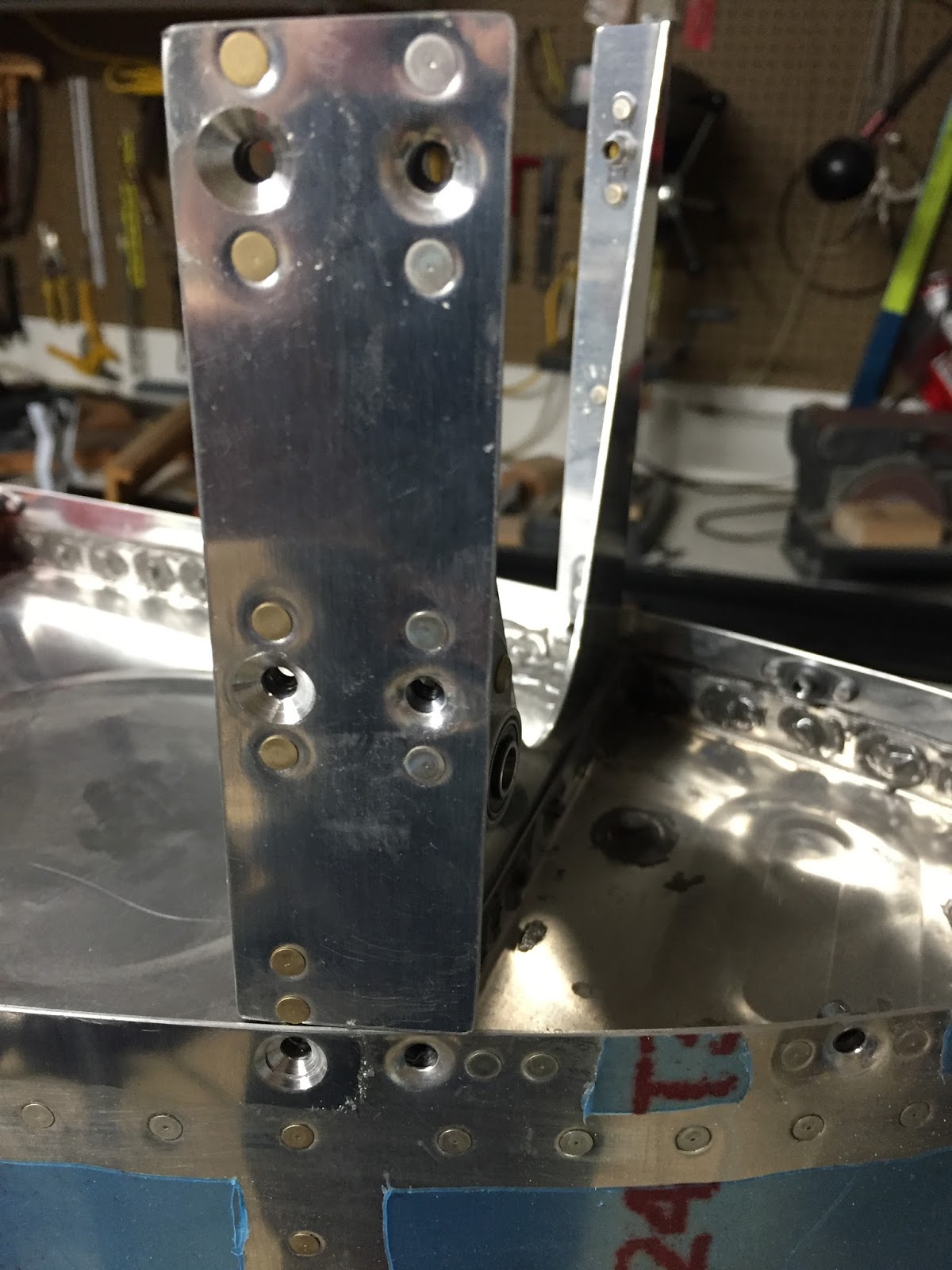
In looking over the rivet call outs, I saw the note about holes for the tie down lugs. I got out the step drill and enlarged the already drilled tie down holes to 3/8".

Next I noticed there were some empty holes in the spar. On further investigation I realized I had overlooked some nut plates that were called out back in chapter 13. They are all the way out at the end of the spar and were off to the side of one of the manual drawings. I counter sank the holes and riveted in the nut plates. It was a little more work moving the spar around now that the ribs, sub spar and top skins are attached.

Section: 16
Hours: 2.5

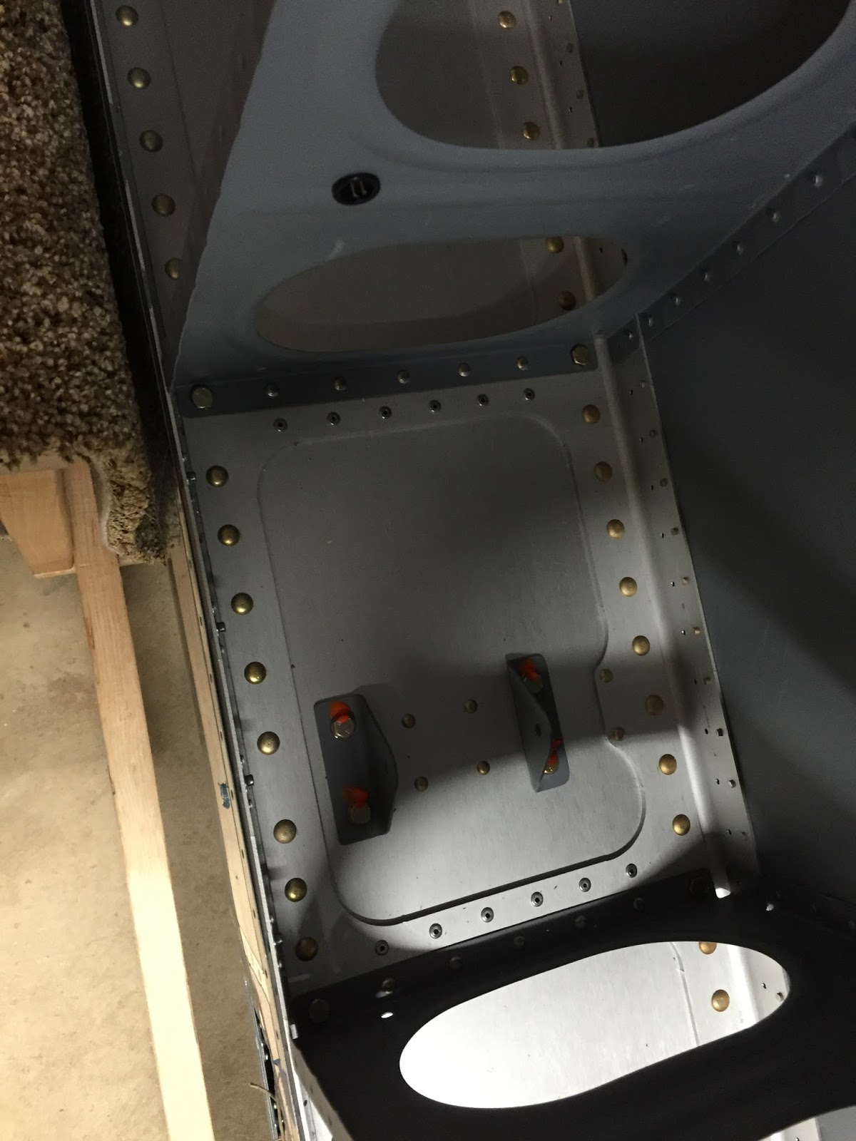
I felt pretty confident that the outboard leading edge assemblies were ready for attaching so I moved on to finishing up the tanks. I counter sank the holes at the inboard side of the tanks using the #8 counter sink and finishing up with the #30 because the #8 would not go all the way to the final depth.

I hadn't done the pressure test yet to check for leaks, so I rounded up all the plugs, drains, strainers, fuel caps, balloons, air valve, thread sealant and a bicycle pump and went at it.

You have to insert plugs in the remaining open holes. I spent some time researching the proper torque values and what sealant to use. After perusing chapter 5 and reading several threads on Van's Airfare it looks like you apply thread sealant and then finger tighten the plugs. Then you tighten another 1.5 to 2 revolutions with the wrench. Same thing for the fuel strainer and the fuel drain plug. Here's the sealant that I bought at the local auto parts store.

I found the gas cap was a little loose, so I tightened the nut on the inside of the cap until I felt a little more force on the locking arm when closing it up. Then I taped over the gas cap with clear packing tape to fully seal it.

Here I've pumped air into the tank just enough to inflate the balloon that is tied to the vent line. The balloon stays inflated for about an hour and then slowly deflates, so I have a leak somewhere. Tomorrow I'll get out the soapy water and spray the tank down to look for leaks. Right now I suspect the balloon is leaking, but the soap will tell.