Showing posts with label fuselage. Show all posts

Wednesday, November 10, 2021

 Section:

Hours: 8

I had a local sign shop prepare registration number decals and I applied them to the vertical stab. I used masking tape on the top edge of the decal to position and hold it in place. Then I removed the back carrier layer and rubbed the letters down and finally I peeled off the top carrier film.


Today I also finished sanding the canopy fillet and spayed on a couple of primer coats. The fiberglass is now completed on the rebuild.

I recently got the replacement foam seals from Van's. They had been back ordered for some time. Today I installed the foam seals and installed the canopy back on the airplane.


Friday, November 5, 2021

Section: 38

Hours: 6

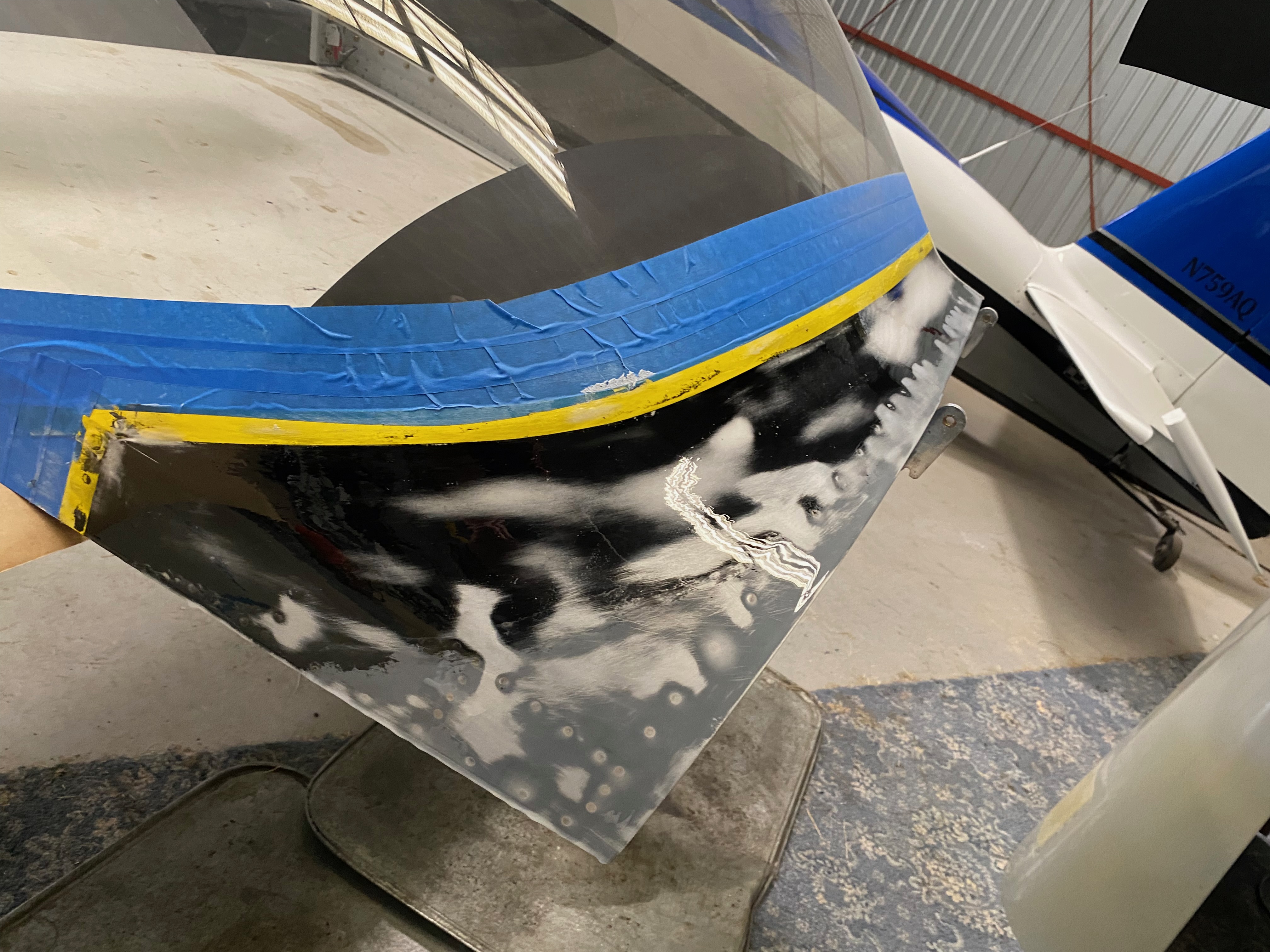
I sanded and profiled the canopy skirt to final shape and applied a top coat of clear epoxy to seal the micro balloon filler.


Saturday, August 21, 2021

 Section: 38

Hours: 4

Here is the new canopy frame next to the old frame. Next up is painting.


Friday, August 6, 2021

Section: 38

Hours: 8

I sanded down the fiberglass layup to match the contours specified in the manual. Then I applied epoxy glass bead filler to smooth over pinholes and build up the contour in a couple low spots. Then I mounted the canopy back on the fuselage and buttoned everything up because I will be taking at least a month off while I go through surgery to donate a kidney to my brother up in Seattle.


Section: 38

Hours: 8

I sanded and roughed up the canopy frame skirt area and plexiglass for fiberglassing, applied an epoxy and  glass bead fillet and then layed up the fiberglass skirt. I used lots of black pigment this time to ensure the view from inside the cockpit will not show any light areas at the fillet area.


Tuesday, August 3, 2021

 Section: 38

Hours: 6

I riveted the side skirts on, inserted the back shims and bolted the plexiglass in place. Everything fit really well and the canopy opens and closes smoothly.


Monday, August 2, 2021

Section: 38

Hours: 6

I transported the plexiglass to the airport and fitted it on the canopy frame. Luckily the rebuilt frame almost exactly matches the original so I did not have to do any reshaping of the plexiglass.


Monday, July 26, 2021

Section: 38

Hours: 7

I was able to fit the canopy frame in the back of my Rav4 and transport it to the airport today. The canopy to fuselage fit appears satisfactory although perhaps not quite as good as the original.


Friday, July 23, 2021

Section: 38

Hours: 2

I applied the anti glare black for the under plexiglass area.


Thursday, July 22, 2021

Section: 38

Hours: 4

I sprayed on epoxy enamel to match the cockpit interior. I used Stewart Systems EcoPoxy Enamel. To get a good finish you lay down a couple mist coats and then do a flood coat which hopefully will flow out to a smooth finish. Hard to do without getting runs.


Tuesday, July 20, 2021

 Section: 38

Hours: 7

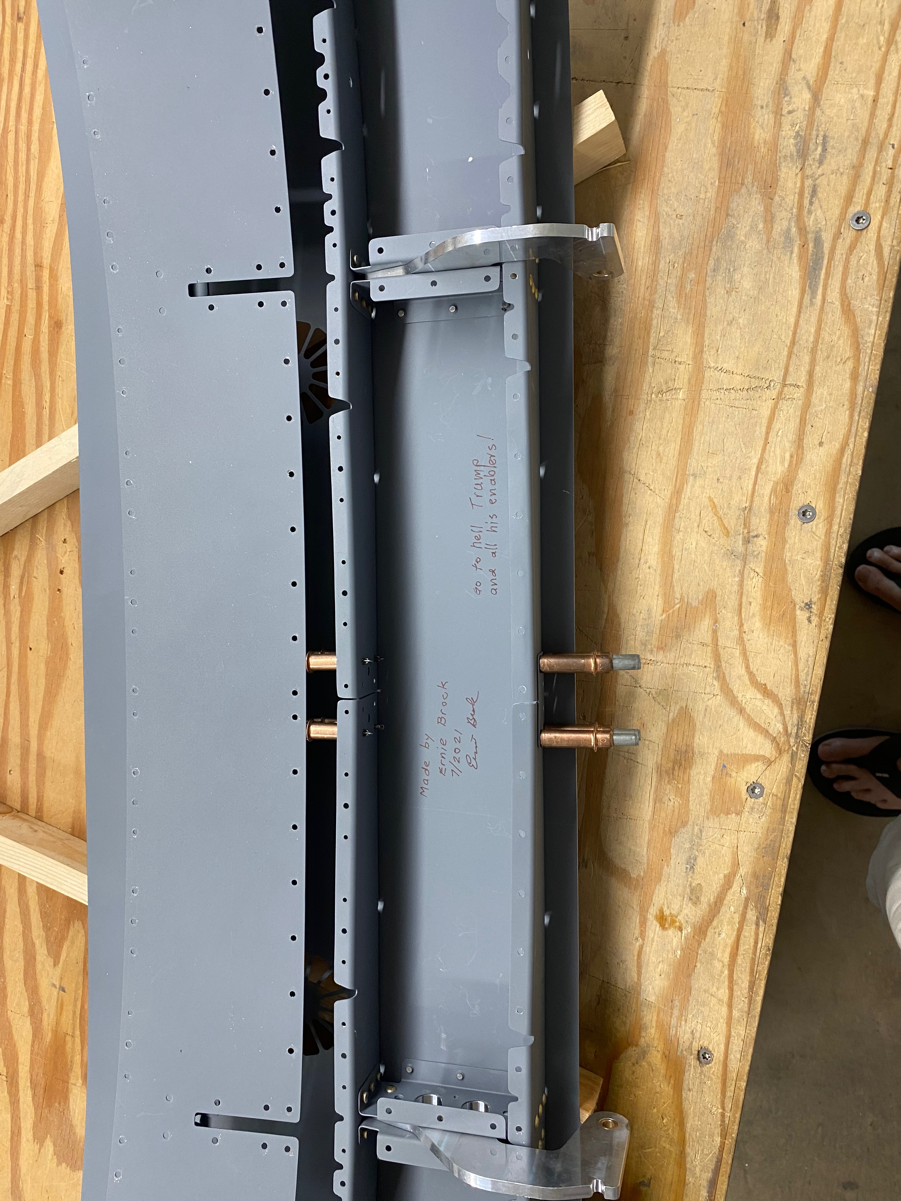
I signed the canopy frame and left a message for prosperity before closing out the inner skin.

Final drilling the inner skin.
All skins riveted. The inner skin cannot be bucked so it gets pull rivets.


Monday, July 19, 2021

 Section: 38

Hours: 7

More counter sinking and riveting on the canopy frame today.


Friday, July 16, 2021

Section: 38

Hours: 8

The 2nd canopy hinge part arrived today!

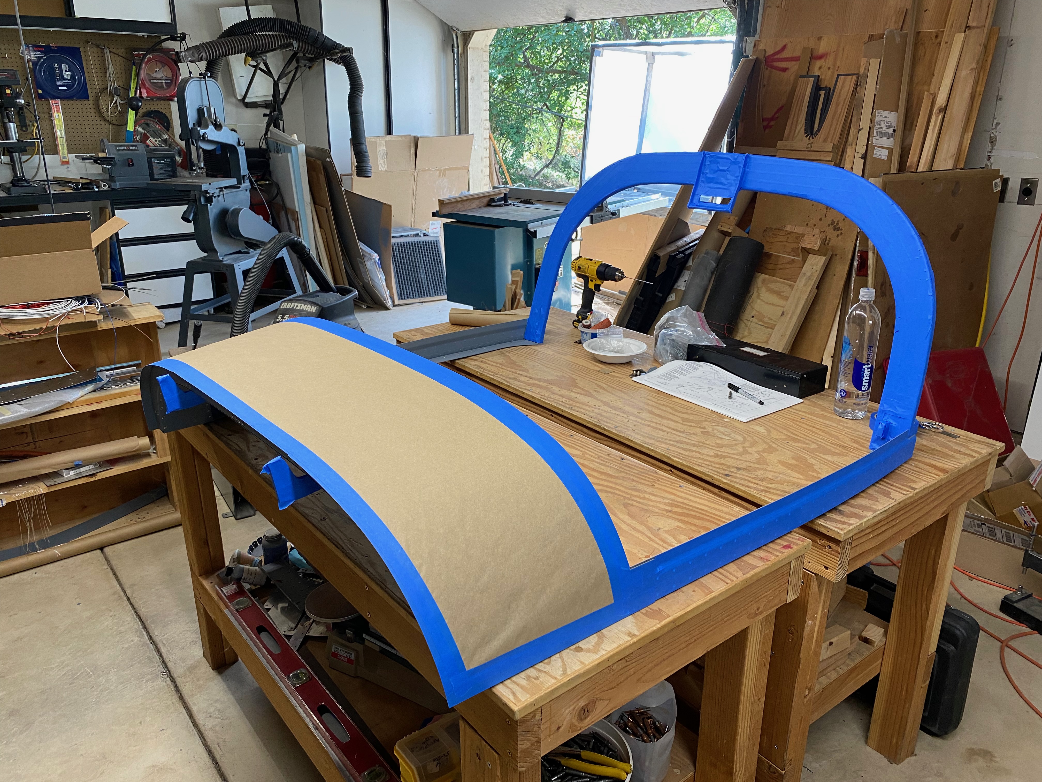
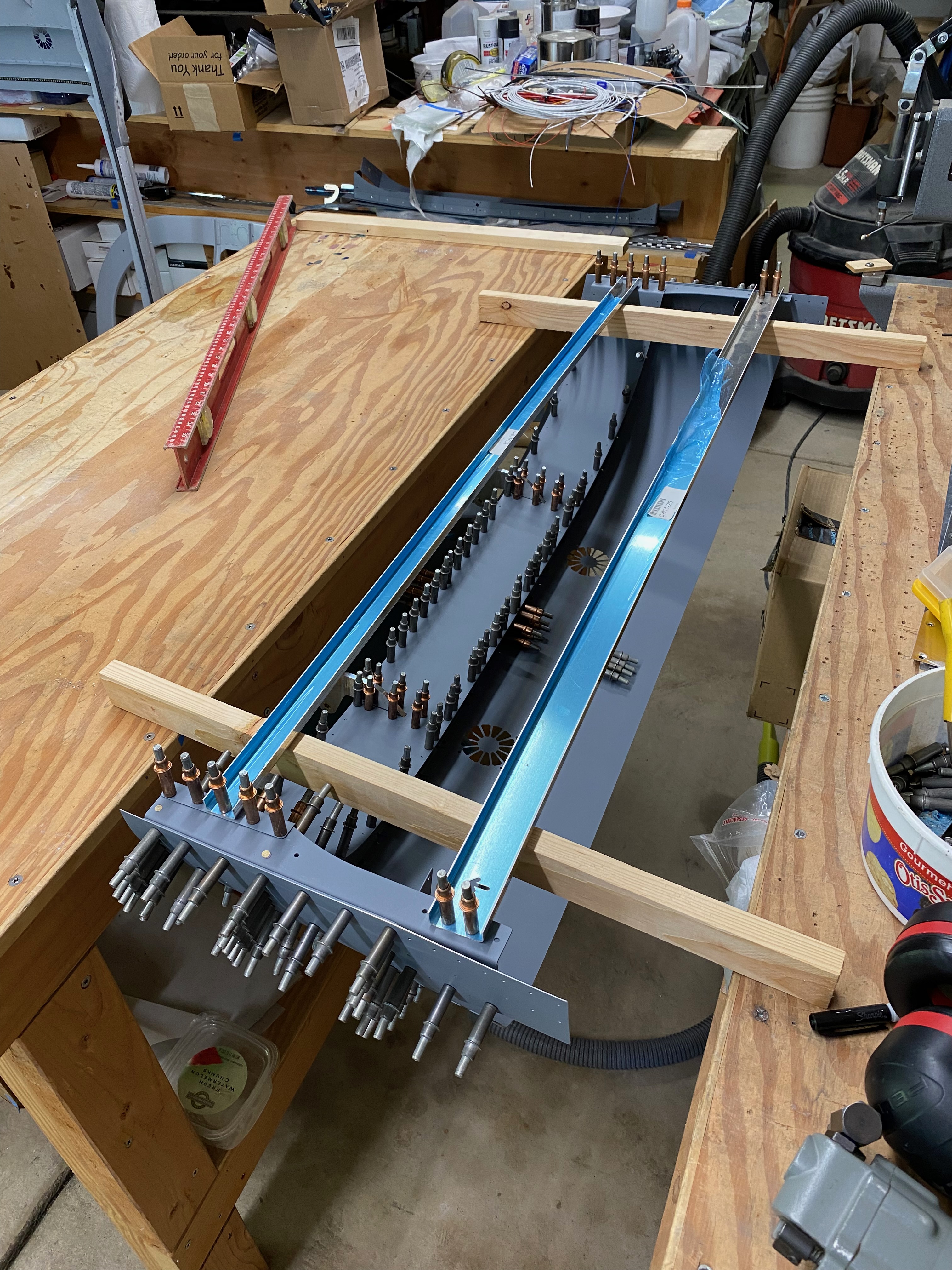
After clecoing the frame and skin pieces together, I hung it between my 2 work benches to make sure there is no twist before doing the final hole size drilling. This insures a straight canopy frame that will properly fit on the fuselage.

Here is the frame assembled with all holes drilled to final size ready for riveting.


Thursday, July 8, 2021

 Section: 38

Hours: 7

I started riveting the canopy together and primed the remaining canopy frame parts today.


Sunday, July 4, 2021

 Section: 38

Hours: 7

I used the Dremel tool with circular cutoff disk to make a couple of slices in the fiberglass fairing skirt on the canopy. Then I carefully wedged toothpicks under the fiberglass to get it to part from the canopy frame and plexiglass. The epoxy does not form a chemical bond to aluminum, so I was able to break the mechanical bond with some effort. This is why it is so important to do a good job of roughing up the aluminum and plexiglass before laying up the skirt.

The skirt cleanly came off in 1 large piece after applying tooth pick wedges under it. Here you can see the glass bead/resin fillet and fiberglass layers and the underlying rough aluminum skin and plexiglass. You can also see the aluminum clips that hold down the edge of the plexiglass.

Here is the plexiglass after removing it from the frame. Luckily it came apart cleanly and I will be able to reuse it.


Thursday, July 1, 2021

 Section: 38

Hours: 8

Deja vu- worked on assembling the canopy frame. I tell all my friends that I'll build my second RV in half the time. Well, that might be a little bit of an exaggeration, but it is definitely easier the second time around.


Monday, May 17, 2021

Section: 38
Hours: 4

Last year was a lost year to Covid. I started my tail wheel training and moved the wings to the airport and then everything shut down. The fuselage was almost ready to transport to the airport but it sat in my garage the whole year.

I got my vaccine shots and I am now ready to got back out in the world and hopefully get the airplane in the air this year.

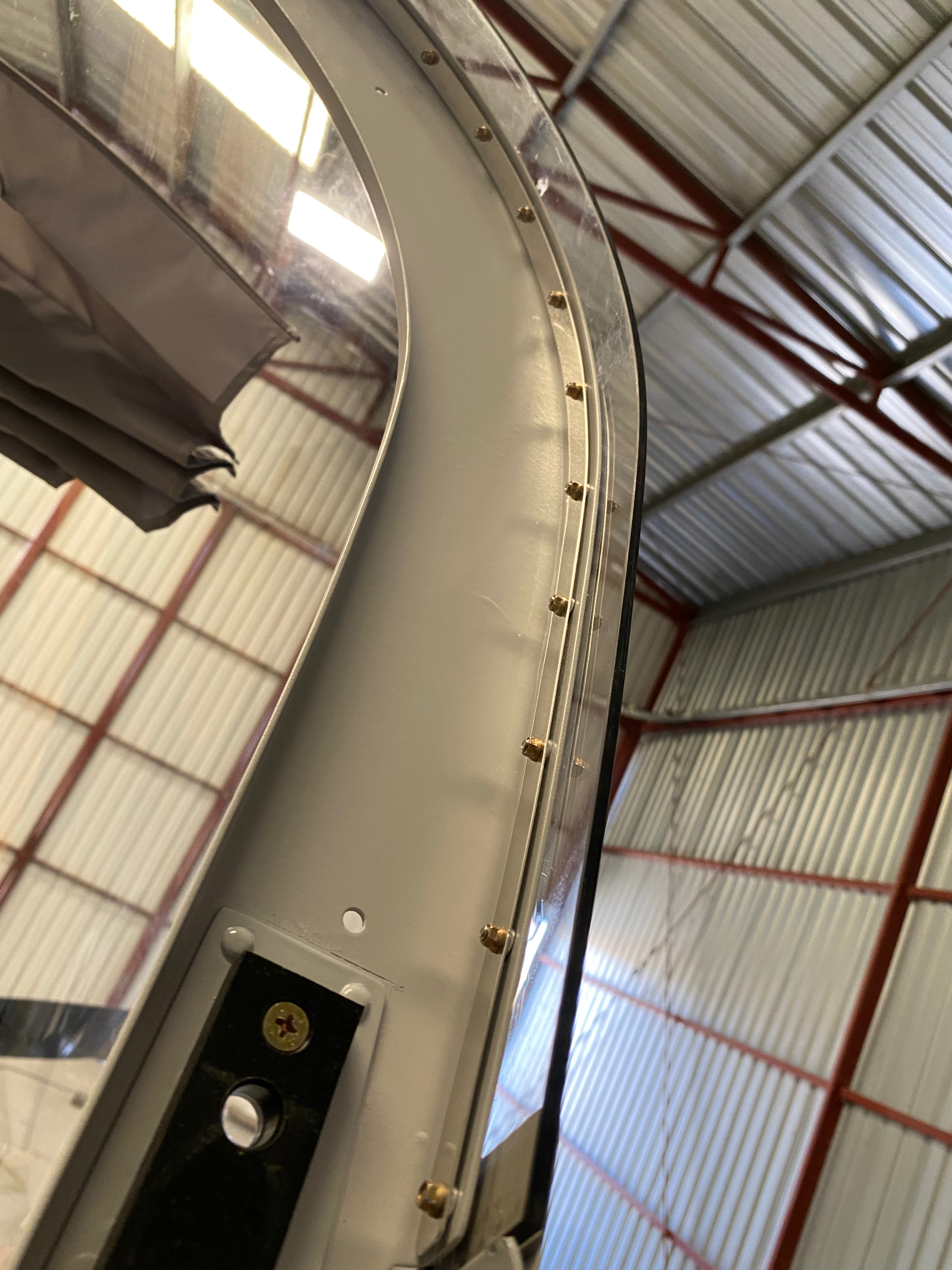
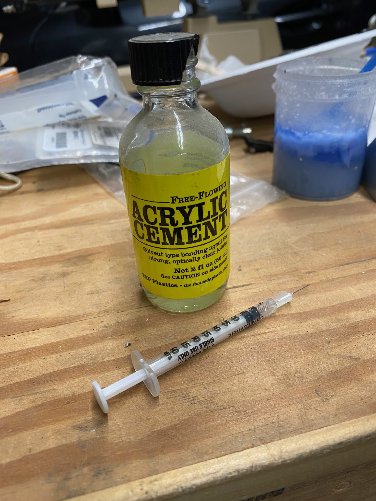
The first task up this year is to get the rear window on. I had left it out to make it easier to work on projects in the cabin, but most of those are done. It was warm today and I worked slowly. I smeared pro seal between the skin and the plexiglass and tightened down the nuts and bolts to a low torque. Everything went well until the very end. A small crack came out of the last bolt I installed. I stop drilled the crack with 1/16" bit, drizzled some acrylic weld from Tap Plastic into the crack and called it a day.


Wednesday, February 26, 2020

Section: 33
Hours: 18

Some of the places I've flown to have inclined parking and often there is a lot of wind when I land at airports away from home. In my Mooney I would simply put on the parking brake until I could hop out and apply chocks to the wheels. Van's does not include a parking brake as part of the standard design for the RV14. I've spent the last couple of weeks noodling out how to install a parking brake and came up with this design:

I added a push/pull cable to the left of the cabin heat on the pilot's side of the control panel.

And I installed a Matco PVPV-D brake valve on the side skin of the fuselage. When you activate this valve, it retains the pressure between the valve and the brakes. If you apply braking using your toes and then throw the valve, it will lock the brakes until the valve is released.

Here are the parts I purchased:

I quickly discovered that the straight hose fittings would not work. The nylon brake tubing will not bend sufficiently to allow attaching straight into the valve. So I ordered 90 degree elbows. I also sourced a cable connector from Aircraft Spruce that would fit on the arm of the brake valve. Here are the parts:

Originally I was going to attach the valve to the longeron that supports the rudder pedal cross tubing, but I ran into trouble routing both the push/pull cable and the brake line connections. A friend who built a 14A attached the valve on the center sub panel support, but for the tail dragger version that is not convenient because the brake lines run to the firewall. I eventually determined the best mounting spot is on the fuselage side skin in line with the control panel bottom so the control cable has a straight shot to the brake arm and also the brake lines can be routed to be out of the way of feet on the rudder pedals.

I drilled 4 holes through the side skin and dimpled them for the mounting screws.

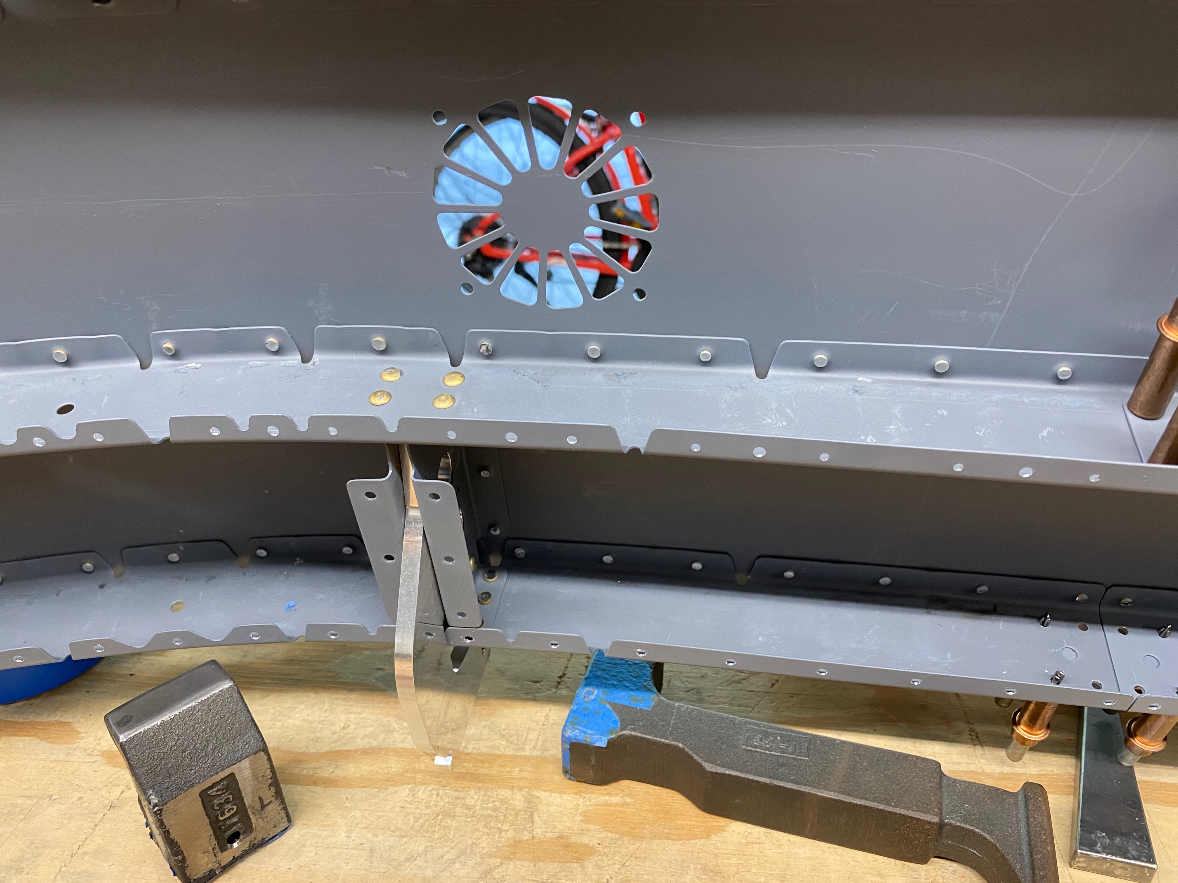
If I had known these holes were needed before assembling the fuselage it would have been a simple matter to dimple them. To dimple them after the fuselage was completed required a different approach. I drilled a hole in a bucking bar so I could insert a dimple die and I took the die holder out of my c-frame and mounted it in my rivet gun.

I was able to enlist Deb because this was a 2 person job- my arms are not long enough. A few taps on the rivet gun with me holding the bucking bar / female die on the other side was sufficient to form the dimples. Thanks Deb!

The valve will completely open /close with 45 degrees of movement of the control arm. I built an aluminum valve mount that sets the ends of the throw and reinforces the fuselage side skin. When the control cable is pushed in to the control panel, the valve is set to the open position and does not interfere with the operation of the brakes. When the control cable is pulled all the way out, the arm hits the stop on the mount and the current pressure in the brake line is retained between the valve and the brakes. 

The cable end I used required washers and a cotter pin to hold it in place. I had to insert several washers to get a good fit and I ended up grinding one of the washers a little thinner to get a really tight fit with no wobble.


I had to fabricate a new line going to the right brake because it was too short to reach. I had hoped to be able to remove the nuts and ferrels from the lines I had already installed, but they were too tight to pull off the nylon tubing without destroying them so I had to order new ones from Vans. I fabricated a new line from the right firewall attachment to the brake valve that is 2 inches longer than the original line. I cut down the length of the line coming from the left firewall connection to fit and fabricated 2 new lines going from the rudder pedals to the brake valve.

I used the nylon brake line tubing provided by Van's. To make a connection to the Matco 90 degree brass elbows you must push the tubing onto a barb and seat the end of tubing all the way into the well of the brass elbow. When I just ran the bit into the end of the nylon tubing I could not keep the reamed out area concentric with the outside of the tube and then could not force the tubing all the way into the well on the elbow. To keep the drill bit centered on the tubing and to keep the tubing round while drilling, I fabricated an alignment jig out of 2 pieces of 1/4 thick aluminum bar with a 1/4 inch hole on one side and the #22 dill hole size on the other.

I drilled and tapped 2 screw holes to hold the pieces together.

To ream out the tubing end, I insert the nylon tubing into the 1/4 inch hole side and then drill from the opposite side. 

The tubing end must be cut square so that it will properly seat at the bottom of the well in the 90 elbow. I drilled a 1/4 inch hole in another piece of 1/4 aluminum bar and used that for trimming the ends of the tubing using a razor blade.
Here's the result.