Showing posts with label avionics. Show all posts

Saturday, November 6, 2021

Section:

Hours: 2

Today I hooked up the static lines to the Garmin ADAHRS and G5


Monday, July 5, 2021

 Section:

Hours: 0.5

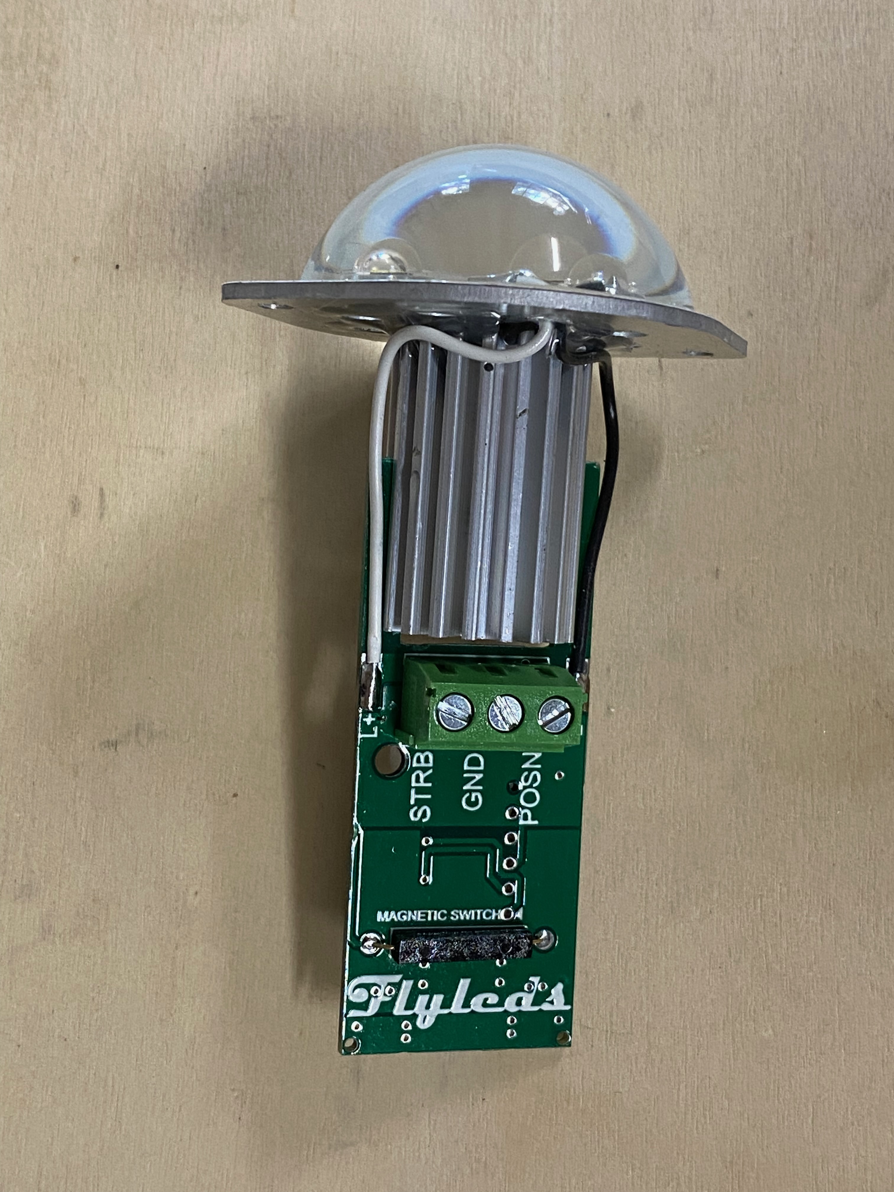
When I checked out the navigation lights I discovered the tail light only operated in strobe mode. I ordered a new tail light from FlyLeds that supports nav plus strobe operation. It also nicely fits in the rudder tail fairing which will simplify installation.


Sunday, March 1, 2020

Section: avionics
Hours: 5

I recently purchased a pitot static toggle valve and a female straight connector from SteinAir. This valve is placed inline of the static line and can be opened in the case that the static ports become blocked (icing, insects, etc). I decided to install the valve on the cable riser panel between the tunnel on the floor and the control panel. I had easy access to the static line there and it will be accessible in an emergency but out of the way otherwise.


I finished the installation by adding a red switch cover to prevent accident switch activation. It also shows at a glance the switch is in the proper position. I made the switch label by printing on a special ink jet transparent label paper. After printing I cut the label to size, removed it from the backing sheet and applied it to the panel.

Tuesday, February 4, 2020

Section: avionics
Hours: 4

I installed a dome light at the back of the luggage storage area. This light is on the map light circuit and is controlled by a dimmer on the control panel. The light is locally grounded to the airframe and the power line comes from the dimmer circuit board in the panel. I discovered I had missed riveting the center 3 rivets in canopy top brace so I tackled that first.

Then I created a support plate and attached the light with 2 screws. I also drilled a wiring hole in the fuselage bulkhead and inserted a through hole plastic insert. The support plate attaches to the canopy brace using 2 more screws with lock nuts. The light is slightly tilted forward so the light nicely illuminates the baggage area. I may build a shade to limit the LED glare to just illuminating the baggage floor.

Tuesday, January 28, 2020

Section: avionics
Hours: 3

The epoxy hasn't cured enough on the canopy so I will let cure for another day.

I decided to wire the connector to the GMU22 today. I pulled out the mounting kit studied the wiring diagram.

The wiring harness leads in the wing already had pins attached.

All I had to do was sort out which wire goes in which connector pin position and insert it.


Monday, January 13, 2020

Section: avionics
Hours: 2

I installed the pitot/static plumbing to the ADAHRS. I had been stumped about how to install the elbows because they ran into each other while screwing them in. Then I discovered that the threaded end twists without rotating the entire elbow body. Duh! White line is static, green is pitot and blue is the AOA.

Sunday, December 22, 2019

Section: avionics, wings
Hours: 5

I finished up the installation of the pitot tube.

Here are the fittings for attaching the plastic lines to the aluminum lines from the pitot. I decided to use 90 degree connectors so the plastic tubing will not have to make a sharp bend at the end.

I bundled up the excess wiring and laced it up.

Here's the inside view of where the plastic tubing attaches.

The pitot wiring would not fit through the existing wiring bushing so I wrapped it with spiral wire protector and ran it through the rib opening.

Here is the mast and pitot after installation. The controller box is under the access plate to the right of the pitot mast.

Friday, December 20, 2019

Section: wings, avionics
Hours: 4

Earlier I installed doublers and cut holes on the inboard side of the aileron belcrank for the pitot mast.  The pitot tubing runs into the aileron push/pull tube unless you bend the tubing out of the way. Today I figured out how to bend the tubing to keep it out of the way of the aileron tube but still allow the pitot tube to be removed from the mast for future maintenance.

I mounted the regulator electronics box to a wing panel access door. Since I am using counter sunk screws for the mounting and the flange on the regulator box is not counter sunk, I fabricated a couple aluminum bar spacers with counter sinks to place between the access door and the box.


Here is the pitot tube inserted in the mast with the tubing bent to avoid interference with the aileron push/pull tube.

Saturday, November 30, 2019

Section: avionics
Hours: 4

Today I finished up some wiring projects. First up was adding the connector cable to the roll servo in the wing.

I discovered the hole in the servo bracket that the connector mounts in was too small. Luckily I was able to reach in with the Dremel and enlarge the hole.

The db connector attaches to the back of the servo and the other connector goes through the servo mounting bracket and then plugs into the wiring harness from the wing.

I also finished up mounting the GMU22 magnetometer in the wing. I used the mounting kit that came with my panel from SteinAir. This kit fits into the ADAHRS mounting plate which inserts into rails built into the wing.

Section: 41
Hours: 1

I had previously prepped and primed the wing/fuselage intersection panels. The panel that wraps around the leading edge must be bent to match the curvature of the wing. I found some PVC pipe of the proper diameter, chucked it up in my vise and easily applied the specified radius bend.

Tuesday, November 12, 2019

Section: avionics
Hours: 8

The wiring harness arrived from SteinAir! It includes a new plug for the cooling fan and a short length of wiring from the old plug to the new one.  Looks good.

I moved the sim card from the old connector to the new one and plugged it in. Then I installed the new harness and put the panel back together again. I'm getting faster at reassembling the panel, but it still took all day :-(

Success!!! The GTN fan now runs. Hopefully my panel wiring woes are behind me.

Wednesday, October 30, 2019

Section: avionics
Hours: 5

I got to the P1001 connector after much disassembly. Not only are the pins bent, but they are loose and easily wobble around in the plug (pins on lower side of connector in photo below).

I do not think this plug can be repaired. I am going to ask SteinAir to wire up a new plug with a harness that will plug into the good pins of the existing connector. I will bypass the broken pins with jumpers directly to the new connector. I will also have to move the cooling fan wires and the sim module to the new plug.

Tuesday, October 29, 2019

Section: avionics
Hours: 7

I am puzzled why the pins on the P1001 connector keep bending. My first thought was that the connector on the back of the GTN was damaged. Here is a picture of the connector. You can see where the bent pins marked the backplate, but the female pins are not obviously blocked.

I was able to insert loose male pins in all the J1001 female pins. There was no blockage.

Next step is to get to the P1001 connector which requires tearing apart the whole panel (again...).

Thursday, October 24, 2019

Section: avionics
Hours: 6

I carefully double checked the wiring and made sure the remaining loose ends were safely shielded. I made sure all the switches on the panel were in the off position and connected the battery.

Then I flipped the battery master and heard the contractor click. The panel then started up! Feeling lucky I also flipped on the avionics and lighting. No smoke escaped!

Everything was looking good but then the GTN650 diagnostics reported this:

The cooling fan failure is a non start. The GTN650 runs hot and the fan is not optional. I pulled the GTN box out of the tray and discovered the connector repair I made had not worked. I had very carefully installed the GTN into the tray and didn't feel any resistance when I plugged it in. Despite all the care, pins were still bent. :-(

Time to contact SteinAir...

Saturday, February 23, 2019

Section: avionics
Hours: 4

I finished up the ground wires for the main panel.

Friday, February 22, 2019

Section: avionics
Hours: 4

I was able to identify all but 8 of the ground wires and added wire labels to them. Today I started adding connectors to the grounds.


Wednesday, January 30, 2019

Section: avionics
Hours: 4

I worked more on engine compartment wiring. Here are the battery and starter contractors and the ANL fuses and shunts for the alternator and backup alternator.

Tuesday, January 1, 2019

Section: avionics
Hours: 4

I connected the wiring for the oil and fuel pressure sensors.

Sunday, December 30, 2018

Section: 50
Hours: 5

I put the radio stack trays back and reassembled the rest of the panel.

Tuesday, December 25, 2018

Section: avionics
Hours: 5

Our kids went to the in-laws for Christmas this year so I got to spend some time in the garage. I extracted the bent pins from the P1001 connector.


Then I removed the bent pins and crimped on new ones.

The red wire was too short to be able to insert the pin back into the shell so I spliced on an extension.


Here is the shell reassembled after inserting the new pins.

Here is the other side after inserting the shell back into the tray. I'm not sure if this is going to work- as you can see the pins on the right side of the connector look a little wobbly. I won't know until I insert the GTN 650 after reassembling the panel.