Section: 18
Hours: 10
I decided to take advantage of the cooler weather today to do some more ProSeal work. ProSeal cures less rapidly when it is cooler which makes it easier to accomplish the work before it starts getting stiffer and stickier and gooier...
First up I installed the fuel level gauges. It took me awhile to figure out that there is a left and a right version. They aren't complete mirror images of each other, but the way they are attached to the mounting flange is different by 180°. I bent one of the legs not accounting for the radius of the bend and the arm ended up too long. I was afraid to straighten the bend so I put a kink in the arm to compensate (left gauge in pic below).
The mounting flange has an irregular spacing for the holes and only aligns with the tank assembly when the "MEXICO" stamping is towards the nose of the tank as seen here. After installing with a 1/16" thick layer of ProSeal you tighten down the screws to get a 1/32" layer. Then you check to make sure the lock washer behind 1 of the screws is properly making electrical contact between the tank and the flange.
Here's the gauge flange with the ProSeal squeezed out all around.
Inside view of the ProSeal squeeze out after tightening the screws.
Here's the left and right tanks next to each other showing the orientation of the gauges.
Here's the tank vent line connection at the inner rib. I initially wasn't sure if the nut that sits in the socket on the rib was supposed to have ProSeal applied. Early in the construction manual chapter it states that all mating parts or any place that fuel can seep through should be sealed with ProSeal. A couple threads on the Van's Airforce web site confirmed this also, so I slathered some ProSeal behind the nut before torquing it down and for good measure dabbed some on the outside of the nut.
Here's the outside of the vent line connection and the fuel gauge plate.
I had to bend the vent line more sharply to leave the required 1/4" clearance from the outside rib.
Now the hard part- I applied a bead of ProSeal using a popsicle stick on the tank skin mating area and the flanges of the end ribs. I also applied a thin dab where the z-stiffener rivets go into the rib flanges on the interior ribs. Then you slide the back baffle in (taking care to properly orient the baffle flange with the "EXTRA" hole on the bottom). Then apply a gazillion clecos and check that the ProSeal is properly squeezed out. If you leave too thick a ProSeal layer it can impact the fit between the tank and the wing spar.
Here's the baffle after clecoing and pulling the rivets on the z-stiffeners.
Then I squeezed the flange rivets leaving every tenth hole with a cleco inserted.
The flanges of the end ribs get solid rivets which I set using the rivet gun and bucking bar. That was especially messy because the ProSeal squeezed out of the end seam while riveting.
Here's the baffle with the rivets set. I haven't dabbed extra ProSeal on the heads of the rivets yet.
Disclaimer: This blog is to provide others insight into my experience and for my own historical purposes. Airplane construction is a serious affair. I have no authoritative skills relating to airplane construction. As such, any use of the information contained on this blog is at your own risk.
Wednesday, April 27, 2016
Friday, April 22, 2016
Section: 16
Hours: 4
Today I finished dimpling the upper wing skins. I also filed and polished the edges of the bottom wing skins.
When I disassembled the left wing, I discovered that I had placed the lower wing walk flipped the wrong way. As a result, the whole panel ended up about 1/4" out of position and some of the holes got doubled. I ordered a small sheet of .025 2024-T3 from Aircraft Spruce to make a replacement.
Woody is always looking for ways to help with the construction. He's really good at sniffing out quality control problems, but he has a hard time with hand tools. Too bad Cleveland Tools doesn't have any paw tools. Today we found a good job for him- removing the blue protective plastic from the aluminum skins.
Hours: 4
Today I finished dimpling the upper wing skins. I also filed and polished the edges of the bottom wing skins.
When I disassembled the left wing, I discovered that I had placed the lower wing walk flipped the wrong way. As a result, the whole panel ended up about 1/4" out of position and some of the holes got doubled. I ordered a small sheet of .025 2024-T3 from Aircraft Spruce to make a replacement.
Left doubler with extra holes on top.
Thursday, April 21, 2016
Section: 16
Hours: 5
Today was spent finishing the prep work on the upper wing skins. The wing skins have a slightly rough edge from the manufacturing process. I file all the edges and then polish using the small 3M wheel in the die grinder.
After finishing the edges there is a whole lot of dimpling to do. One of the biggest time consuming parts of dimpling is aligning the hole with the dimple die hundreds of times in a work session.
Another RV14 builder added a laser sight to his DRDT2 dimpling frame and I was considering doing the same. You can purchase laser cross hair components and it would be a simple circuit to construct- just a battery, switch, couple resisters... Then I started thinking about having to replace batteries, mounting, ordering, etc. and realized that was overkill.
Here is my simple mechanical hole finder. It consists of a short piece of insulated copper wire with a jewelry bead epoxied to the end. The whole affair is attached with some 100mph duct tape and can be easily adjusted using simple finger pressure.
I adjust the bead so it floats close to the edge of where the dimple die pin is located. When the piston is lowered, the bead gets pushed to the side and snaps back to position when the piston is raised. The wire is flexible enough so that I can easily move the wing skin around, but as I get close to aligning the next hole the bead accurately indicates where the pin is. This simple device easily doubles my dimpling speed.
Dimpling in action.
Woody looking for missed dimples. Today was a good day- he didn't find any.
Wednesday, April 20, 2016
Section: 16
Hours: 4
The rivet holes in the wing walk area of the top skin get counter sunk because it is two layers thick. The top skin counter sink results in close to a knife edge so you have to be careful with this operation. I used my variable speed electric drill and went slowly.
I trial fit the outer top wing skin panel- beginning to look like a wing!
The goal of the feathering is to have the skin edge match the thickness of the tank skin which will be butted next to it. Here is a scrap of aluminum the same thickness as the tank skin placed next to the scarf joint.
Hours: 4
The rivet holes in the wing walk area of the top skin get counter sunk because it is two layers thick. The top skin counter sink results in close to a knife edge so you have to be careful with this operation. I used my variable speed electric drill and went slowly.
I trial fit the outer top wing skin panel- beginning to look like a wing!
The inner and outer wing skins overlap by about an inch and a half. The construction details specify that you feather the forward corner of the overlap to form a scarf joint. After much filing and sanding, here is the result.
The goal of the feathering is to have the skin edge match the thickness of the tank skin which will be butted next to it. Here is a scrap of aluminum the same thickness as the tank skin placed next to the scarf joint.
Tuesday, April 19, 2016
Section: 15
Hours: 2.5
Today I riveted the wing sub spar to the ribs and finished up section 15.
Section: 16
Hours: 2.5
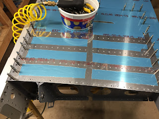
I started section 16. Here the inboard top wing skin and the wing walk doublers are clecoed to the wing. I final drilled all the holes common to the skin and the doublers and also drilled holes for the nut plates that will attach to the inboard edge of the skin. My pneumatic cleco insertion tool came in handy today (attached to yellow hose).
I'm working on the left and the right wings simultaneously. Once you figure out how to do a set of operations on one wing it's easy to do the second. I have the wings arranged so they are mirror imaged which makes it easy to transfer between them.
Hours: 2.5
Today I riveted the wing sub spar to the ribs and finished up section 15.
Section: 16
Hours: 2.5
I started section 16. Here the inboard top wing skin and the wing walk doublers are clecoed to the wing. I final drilled all the holes common to the skin and the doublers and also drilled holes for the nut plates that will attach to the inboard edge of the skin. My pneumatic cleco insertion tool came in handy today (attached to yellow hose).
I'm working on the left and the right wings simultaneously. Once you figure out how to do a set of operations on one wing it's easy to do the second. I have the wings arranged so they are mirror imaged which makes it easy to transfer between them.
Monday, April 18, 2016
Section: 15
Hours: 6
Here I'm using a 5/8" and a 7/16" socket and my vise to seat a bearing in the aileron bracket inner support piece. The bearing body is a tight fit, but once properly inserted, the bearing moves freely.
These three pieces get riveted together and combined capture the bearing. The pockets in the side pieces still had clearance even after priming, although, I was careful not to load up too much primer in the sockets.
Here are the left and right wing, inner and outer aileron support brackets.
Before attaching the sub spars to the wing, you rivet the doubler pieces to the spar leaving empty holes where the ribs will be riveted later.
Here is how the aileron support brackets attach.
Here's the spars with doublers attached. Tomorrow these will be riveted to the ribs.
Thursday, April 14, 2016
Wednesday, April 13, 2016
Section: 15
Hours: 6
Today we continued work on the sub spar assemblies. I matched drilled several doubler plates. One of the plates has a hole for the aileron pushrod that has to be cut. I traced the hole shape from the spar and then drilled a couple rough holes using the step drill.
When I purchased my Dremel I also ordered a set of bits from Amazon. The set included a bit that looks like an end mill, which I chose to rough out the hole.
I clecoed the doubler to the spar which already has the proper sized pushrod hole. Then I used Dremel to hog out the hole to approximate size.
Then I finished up with the sanding drum tool.
Here's the final cut after running the sanding drum over it.
There are several heavy doublers that I straightened and then dressed the edges.
After all the hole drilling, deburring, edge dressing and straightening, Woody and I clecoed the sub spar onto the left wing. Now it looks like we are making progress!
We also assembled the right wing. Tomorrow we will final drill holes and do some more countersinking, but that is a task that requires some early in the day clarity of thought and vision.
Subscribe to:
Posts (Atom)


