Section: avionics
Hours: 5
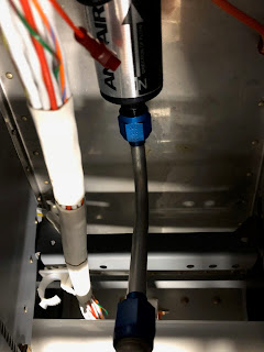
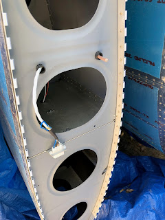
I fabricated a harness for connecting the FlyLeds controller board to the left and right wing.
I will run the yellow wire to one of the grounding tabs on the panel. Power will be picked up from the cabin wiring harness.
Disclaimer: This blog is to provide others insight into my experience and for my own historical purposes. Airplane construction is a serious affair. I have no authoritative skills relating to airplane construction. As such, any use of the information contained on this blog is at your own risk.
Sunday, July 29, 2018
Friday, July 20, 2018
Section: 47
Hours: 2
The snorkel is supposed to be aligned with the fuel injection servo. Then you match drill the snorkel flange to the fuel injection servo flange. I fabricated an aluminum jig with a circular wood plug the size of the snorkel inlet to aid with alignment.
Hours: 2
The snorkel is supposed to be aligned with the fuel injection servo. Then you match drill the snorkel flange to the fuel injection servo flange. I fabricated an aluminum jig with a circular wood plug the size of the snorkel inlet to aid with alignment.
Here the jig is duct taped to the field injector servo. When I mount the snorkel, it will automatically center on the jig.
Wednesday, July 18, 2018
Section: avionics
Hours: 4
I worked on the wing wiring harnesses and started working out how to connect the FlyLeds (white coax) and pitot heater (red/black twisted pair) wiring.
Left wing root:
Right wing root:
Hours: 4
I worked on the wing wiring harnesses and started working out how to connect the FlyLeds (white coax) and pitot heater (red/black twisted pair) wiring.
Left wing root:
Right wing root:
Tuesday, July 17, 2018
Section: avionics
Hours: 5
I tried running the cabin wiring with the elevator and control stick pushrods in place, but there just wasn't enough room. Unfortunately, the wiring end connectors are already attached and it is impossible to squeeze them through the central tunnel when the push rods are in place. It was a hard job putting these push rods in place and it was equally hard removing them. I'm sure it will be difficult to put them back in after the wiring is done :-(
The wiring going to the wing will have to be modified to attach to the FlyLeds...
Section: avionics
Hours: 3
Started laying out the cabin wiring harness. Stein provided the Van's standard cabin harness along with the rest of my panel. It connects to the panel harness with 2 large connectors up front. It will require some modification to work with the FlyLeds strobe and nav light system...
Hours: 3
Started laying out the cabin wiring harness. Stein provided the Van's standard cabin harness along with the rest of my panel. It connects to the panel harness with 2 large connectors up front. It will require some modification to work with the FlyLeds strobe and nav light system...
Friday, July 13, 2018
Section: avionics
Hours: 8
I routed and connected some of the wiring harness today. Here is the starting point. The harness is located behind the sub panel with individual cables threaded forward to their appropriate boxes.
Here I've attached cables to the pilot's side of the panel going to the GEA 24 and the panel switches.

Here is the co-pilot side with cables for VPX, dimmers, etc. I ended up mounting the circuit board with the dimmer circuits towards the top of the center bay side wall. None of the ground wires in the big bundle of black wires are labeled! Bummer, I'll have to sort those and label them.
Hours: 8
I routed and connected some of the wiring harness today. Here is the starting point. The harness is located behind the sub panel with individual cables threaded forward to their appropriate boxes.
Here I've attached cables to the pilot's side of the panel going to the GEA 24 and the panel switches.

Here is the co-pilot side with cables for VPX, dimmers, etc. I ended up mounting the circuit board with the dimmer circuits towards the top of the center bay side wall. None of the ground wires in the big bundle of black wires are labeled! Bummer, I'll have to sort those and label them.
The coiled wire bundle has wires for smoke pump, cabin lights and some other things I'm not sure about. Stein provided a generic schematic of how wires run between connectors to the various avionics boxes, but not a drawing of the actual harness that was built. I will have to contact Stein to find out what the mystery wires are for.
Here is a view from the top center.
Beginning to look like a panel!
Tuesday, July 10, 2018
Section: avionics
Hours: 5
I mounted the instrument panel and then aligned the aluminum radio stack side wall with the bottom of the radio stack opening.
I clamped it in place and used it as a drill template for holes into the side walls between the sub panel and panel.
Next I mounted the VPX box. It was over 100 in the garage, hence the head band to keep sweat from dripping on the expensive $$$ electronics.
Hours: 5
I mounted the instrument panel and then aligned the aluminum radio stack side wall with the bottom of the radio stack opening.
I clamped it in place and used it as a drill template for holes into the side walls between the sub panel and panel.
I then mounted the trays using screws and lock nuts. Here are the trays mounted with the radios inserted. Note that the aluminum side walls provide support for a couple of mounting holes that would have landed in the cutout of the panel support sidewalls.
Next I mounted the VPX box. It was over 100 in the garage, hence the head band to keep sweat from dripping on the expensive $$$ electronics.
Monday, July 9, 2018
Section: avionics
Hours: 8
Today I finished the connector at the wing tip for the lights. I've been using these solder seal connectors for running a pigtail out from the coax shield for grounding. Works great.
I mounted the GAD 29 ARINC box to the sub panel on the co pilot side. I riveted nut plates to the back so it will just screw into place.
I tried several methods for laying out the trays for the central radio stack. Some builders recommended taping the trays together and then match drilling to the walls between the panel and sub panel on the sides of the stack. I was not confident that I could accurately mount them that way. So I got the dimensions of each of the trays from the Garmin installation manuals and produced a drawing showing where all the holes should be.
I then cut two sheets of aluminum that will form side walls for the radio stack. I carefully laid out the hole pattern on the aluminum and drilled pilot holes. I will then use this to drill holes in the formers between the panel and sub panel.
Sunday, July 8, 2018
Section: avionics
Hours: 5
I built some plywood foot well covers so I will be able to lie on my back under the panel while routing the harness.
Here I've mounted the TCW backup battery on the back of the sub panel next to the map box using the clips I previously constructed.
I spend the rest of my work time familiarizing myself with the wiring harness. Some assembly required...
Saturday, July 7, 2018
Section: avionics
Hours: 5
I mounted the GEA 24 to the back of the GTX 45R tray. Then I trial fitted the instrument panel and started puzzling out how to run the harnesses. SteinAir does not provide any instructions for installation...
Hours: 5
I mounted the GEA 24 to the back of the GTX 45R tray. Then I trial fitted the instrument panel and started puzzling out how to run the harnesses. SteinAir does not provide any instructions for installation...
Wednesday, July 4, 2018
Section: avionics
Hours: 4
I completed mounting the Garmin GTX 45R tray. I riveted nut plates on the back of the sub panel and screwed the aluminum channel/ angle brackets on. The marker line on the sub panel shows where the canopy frame extends when closed. The brackets have to clear the canopy frame.
The tray is angled so that the GTX 45R can slide out over fuselage side rail.
Tuesday, July 3, 2018
Section: 47
Hours: 2
I installed the tension rods at the bottom of the baffles.
Next I installed the fuel injector servo, main fuel line and began fitting the fiberglass snorkel.
Hours: 2
I installed the tension rods at the bottom of the baffles.
Next I installed the fuel injector servo, main fuel line and began fitting the fiberglass snorkel.
Subscribe to:
Posts (Atom)


