Saturday, February 24, 2018

Section: 24
Hours: 7

I spend a couple hours hunting and gathering electrical components this morning. I ordered molex connectors for the wing tips, molex pins, shrink insulation, heat gun, crimp on connectors and Dymo wire label shrink tubing from Amazon.

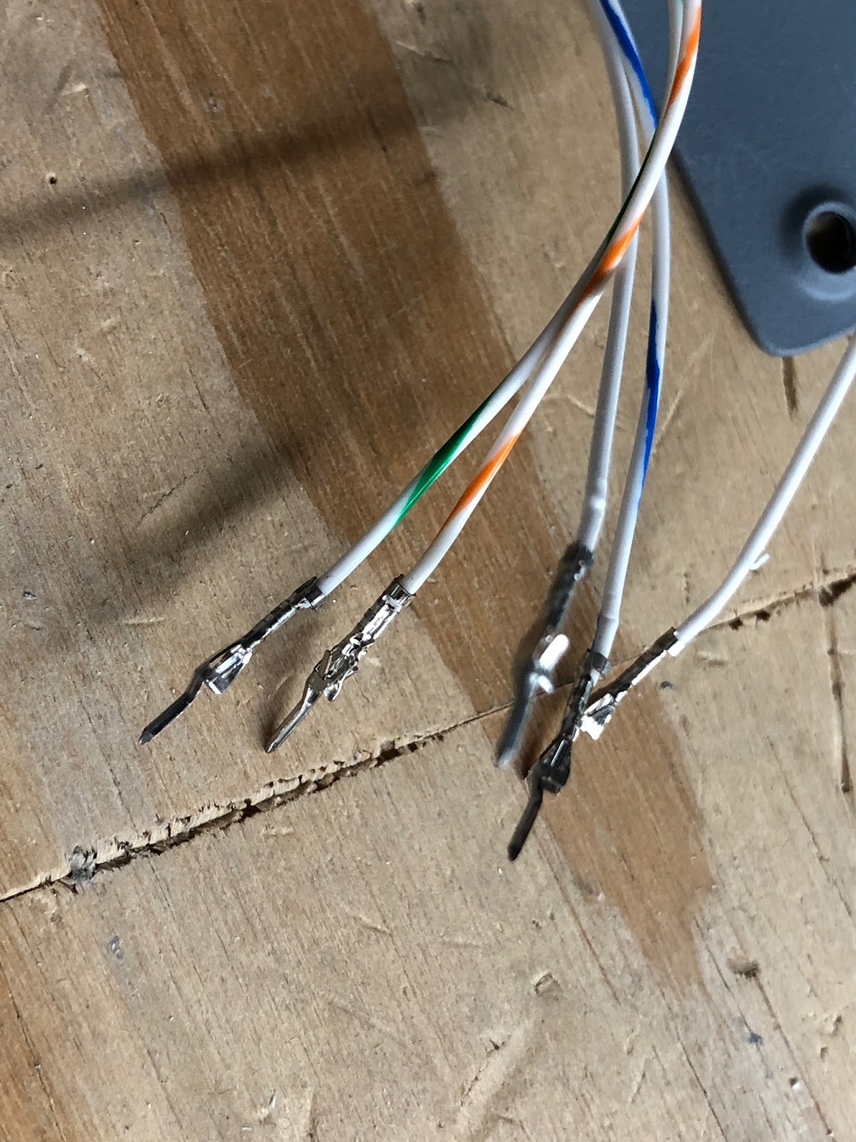
It still hadn't warmed above freezing in the garage after the order session so I watched the tutorial on crimping molex mini pins on SteinAir's web site and added connectors to the aileron trim servo. Thank you SteinAir! The mini pins are very difficult for my old eyes to focus on - I'll have to get one of those big magnifying glasses if I have to do very many more of these :-(
I've been trying to get as much finished in the interior of the wings as possible before riveting the bottom skins. I could probably do a lot of tasks by reaching in through the access holes, but it is MUCH easier with the skins off. I'm now waiting for parts to arrive from Amazon and Aircraft Spruce and hopefully I'll be done with interior work by the end of next week.

This afternoon I trimmed the left wing tip and fitted it to the wing. The first step was to bolt the rigging template to the end of the aileron to hold it in the neutral position. I fabricated a half washer and added a couple spacing washers to space the template from the end of the wing before tightening the nut. Then I used masking tape to hold the template on the aileron.

It took 3 or 4 trim, mount, mark and re-trim sessions to get an acceptable fit. I used a strap to apply (gentle) pressure to force the wing tip into the leading edge of the wing. I also used duck tape to help pull the tip flush into the end of wing.

The fiberglass is very flexible and is easy to coerce into shape. I had read several blogs where the builders had to split the trailing edge of the tip to get it to line up with the aileron trailing edge. I discovered that depending on how you pull the lower and upper edges of the tip into the wing skins you can cause the trailing edge to move several inches up or down.

I squared up the inside edge of the flanges where they meet the wing skins using a sanding block to get a closer fit. Then I carefully used duct tape to pull the tip in for as close a fit as possible. It took a couple times of sanding and looking for interference points before I got a decent fit. Then I used duct tape to pull the tip in as close possible.
At this point the trailing edge was very close to alignment with the aileron trailing edge (see picture above). To get it into final position I gently pulled on the trailing edge of the fiberglass tip and re-set several of the duct tape strips to hold it in final position (picture below).
Finally I drilled #40 the mounting holes starting from the leading edge working aft, alternating between the upper and lower skin. I frequently checked the tip trailing edge alignment as I drilled and clecoed the holes. The alignment ended up spot on by the time I finished drilling and clecoing.


Thursday, February 22, 2018

Section: OP-38
Hours: 4

The paint cured on the parts I painted yesterday after being in the warm house overnight. This morning I riveted together the electric aileron trim module. I was able to squeeze all the rivets which made it pretty easy.

After lunch I puzzled out how to attach the Garmin GAP-26 plumbing to the pitot and AOA lines. I was going to just order a duplicate of the fittings Van's provides for the kit pitot tube, but I discovered they are sized for 1/4 inch tubing and the GAP-26 has 3/16 inch tubing. I started looking for the proper AN fittings in the Aircraft Spruce catalog - there a lot of choices. Then I remembered I had a lot of plumbing parts left over after installing the static ports. I had ordered the Avery EFIS System Plumbing kit from Aircraft Spruce when I was working on the tail cone. It turns out that it has fittings for the GAP-26 aluminum to plastic tubing connections.
 I pulled the pitot and AOA lines through the wing. Then I worked on installing the aileron actuator on the end of the wing. I had cleaned and primed the tubes a couple days ago. The tubes had been a close fit before painting and now they didn't fit at all. I spent a couple hours sanding primer off to get the tubes to fit together again and then applied a good coat of grease and slipped them together. When I went to fit them in the end of the wing I discovered I had to sand even more because you need to slip the inner tubing well past the mark to get the assembly to seat in the bearings.

Wednesday, February 21, 2018

Section: 20
Hours: 7

I worked on fabricating and installing the pitot mast. I purchased the Gretz kit with the holes drilled from Aircraft Spruce (some assembly required). The Garmin GAP-26 heated pitot fits nicely in the Gretz mast. The kit includes the mast, mounting plate, spacer and a bag of nut plates and screws.
The mounting plate comes with a z-bend so it will fit over the spar flange. I lined up the plate so that 4 holes in the spar flange lined up centered on the mounting plate. The mounting plate is riveted to the spar flange, the bottom skin and to an angle bracket that ties to the outboard rib.
A rivet layout fan was included with my original tool kit and today was the first time I actually needed to use it. Works great! You drill the holes on either end of the line, cleco the fan in place and use the fingers to drill the rest of the holes.

I fabricated the rib to mounting plate angle from some scrap .063 sheet I had lying around. I dimpled all the holes in the bottom skin. For the mounting plate, I counter sank the holes that go to the angle brace and dimpled the rest.
 Here is the back showing how the angle brace ties to the rib.
I spent the rest of the afternoon scrubbing, etching and painting parts for the various assemblies going into the wing. I've been using the Stewart EcoPrime water based primer and I couldn't tell if the paint was drying or freezing- it was cold today. I took the parts inside the house to warm up and cure after this picture was taken.

Tuesday, February 20, 2018

Section: 20
Hours: 3

I riveted together the ADAHRS mounting tray and fit the magnetometer bracket. After riveting the tray together I tried to slide the magnetometer bracket in. Unfortunately, the fit was too snug because I made the flutes in the retainer covers too deep. I tried flattening them with pliers, but even then the fit was too tight. I ended up filing down the edges of the bracket to get a better fit. I should have tried the fit before riveting the tray together. Live and learn...


Section: 19
Hours: 2

I decided to run the Van's supplied light and tip strobe wiring through the wing today so I could get an idea of how it fits. I like how the connector fits into a support bracket at the wing root.

I think I will pull out the red, yellow, green and white nav/strobe wires and replace them with a 3 wire shielded cable to eliminate noise. I'll tie the shield to ground on the FlyLED's controller in the fuselage and the shielded cable should fit in the existing grommets in the ribs along with the head light wiring.

Monday, February 19, 2018

Section: OP-38
Hours: 2

I purchased the optional aileron trim kit OP-38 from vans. It includes hardware and a few aluminum parts and a Ray Allen trim servo. When I ordered it I didn't realize the kit also included an LED indicator and an on/off switch for the panel. I will be controlling the trim using the hat switch on the top of the control stick and the G3X display will show the trim status so the included LED indicator and on/off switch will go unused. I would have been $$ cheaper to order the trim servo without the switch and LED.

Section: OP-52A
Hours: 1

I also purchased 2 of the Aero LEDS Sunspot LX landing light kits which include the LED lights, mounting brackets and assorted hardware. Unfortunately I could not find the 2 baggies that have the hardware so I will have to contact Van's tomorrow after the holiday.

Section: 62
Hours: 1

Van's recently introduced a mounting kit for the Garmin GMU-22 Magnetometer. It includes a mounting bracket that replaces the Dynon ADAHRS mount in the left wing. The wing wiring for the Dynon ADAHRS can be repurposed to attach the GMU-22 so it seems like a good deal. Some builders have reported interference from the wing tip strobes causing the GMU-22 to fail, but I'm running an extra pair of shielded wires to my strobes so hopefully that won't be an issue.
Note: The mounting ring for the GMU-22 is not included in the kit from Van's. I ordered all my avionics from SteinAir and they provided the GMU-22, but it did not include the mounting ring either. I'll have to talk to SteinAir about providing the ring.

Sunday, February 18, 2018

Section: 23
Hours: 5

I continued work on the aileron actuator. Here is the jig I used for setting the length and angles before drilling the bolt holes in the center tube. I marked the dimensions on my table and clamped a couple squared off blocks at either end of the width. It was easy to insert the parts and expand them to the proper width. I then used another wood block cut on my table saw to be 1 1/32 inch wide to set the angle per the drawing in the manual. Make sure you build the second one as a mirror image of the first.
I deburred, sanded, cleaned and primed the components with Rust-oleum clean metal primer.

Saturday, February 17, 2018

Section: 23
Hours: 6

We are having more unseasonable warm weather (70 degrees in the afternoon) so I decided to prep and prime some parts. Here are the aileron push rods and end caps, the GMU-22 magnetometer mounting bracket, wing tip ribs and the elevator gap closure fairings. I also spent some time cleaning up the garage some.

I also spent some time working out more details for the wing wiring. I will be using the Van's provided wiring harnesses since I already have them on hand. From my initial research it looks like I will have to provide additional wiring for several items:

1) The FlyLEDS wingtip LED strobe lights may be electrically noisy so it is recommended that they be wired using a shielded pair of 18-22 ga. wire.

2) I will be installing a GAP-26 regulated pitot heater that requires additional wiring runs for power and the sense line that attaches to a G3X annunciator.

3) I think I'll be mounting the outside air temperature (OAT) in the left wing and it will require extra wiring.

4) I am going to use an Archer nav antenna embedded in the right wing tip and it will require a coax cable run.