Section: 12
Hours: 4
This morning I got out the rivet gun, bucking bar and drove some rivets. It's been a while but it all came back to me - like riding a bicycle at this point in the project.
Section: 23
Hours: 3
This afternoon I started work on the aileron linkage. Here I've installed the aileron bellcrank. The first time I started tightening the end nut the bell crank got tight, so I removed it and lightly sanded the inside of the pivot tube. It now moves freely without any slop.
I had previously started the fabrication of pushrods. Today I cleaned out the inside of the tubes with sandpaper wrapped around a broom stick and then taped off the ends and poured epoxy primer into the tubes. Tomorrow I'll prime the outsides.
Next I fabricated the push rods. I had previously primed the inside of the tubes. The threaded ends are held in with (long) AN470AD4-11 rivets. The manual advises using a hand squeezer on these because it is easy to lean them over. I don't have a hand squeezer so I decided to back rivet them, which worked really well. I placed the back rivet plate on the table, inserted the rivet and then held the rod in one hand so the rivet was vertical to the rivet plate and the rod was parallel to the plate. Then I aligned the rivet gun vertically on the end of the rivet and gently tapped the rivet into the back plate to get the initial set. It was easy to control the rivet using this setup.
I finished up this afternoon by inserting threaded rod ends into the torque tube sub assemblies with pull rivets.
Disclaimer: This blog is to provide others insight into my experience and for my own historical purposes. Airplane construction is a serious affair. I have no authoritative skills relating to airplane construction. As such, any use of the information contained on this blog is at your own risk.
Showing posts with label Section 12. Show all posts
Friday, February 16, 2018
Thursday, February 15, 2018
Section: 12
Hours: 8
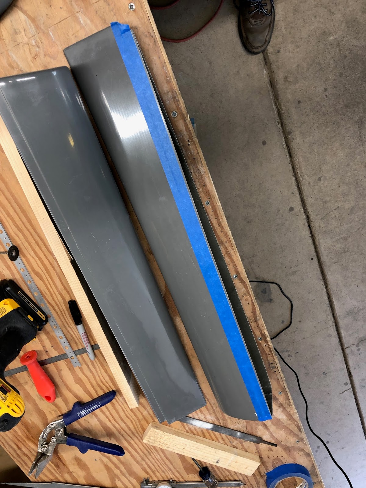
After fitting and match drilling the empennage fairing you do a final trim. You must maintain at least 3/16 inch of margin to the center of all the screw holes. A couple holes on one side of my fairing were too close to the edge, so I had to adjust the trim line out about 1/16" in a couple places. That's why you leave a 1/8 inch margin in the initial trim. I used masking tape to mark the required trim line and cut within 1/16" with the dremel. Then I used a long board with sandpaper to sand to the tape line for a nice straight final trim.
After sanding all the edges to the final trim, I rechecked the fit on the airplane and made a few more adjustments in the saddle areas to close all the gaps to less than 1/32 inch all around. Then I applied a half round to all the edges using a sanding block to first apply a 45 degree bevel all around and then I knocked the edges of the 45 bevel off with the sanding block. I did the final rounding using sandpaper held in my fingers. I should mention that I frequently run the shop vac to keep the fiberglass dust from accumulating (did I mention I hate fiberglass dust ?).
The next step is to add nut plates to the h-stab, v-stab and fuselage. I was able to use the squeezer to rivet the nut plates on the h-stab and v-stab. Then, as I was inspecting the fuselage under the horizontal stabilizer, I discovered that I was missing a row of rivets (see felt marker arrows below). I must have mis-read the manual a few chapters back. There was no way I could do all that riveting with the tail feathers in place so I spent the rest of the afternoon removing the elevators, h-stab and v-stab :-( Two steps forward, one step back...
Hours: 8
After fitting and match drilling the empennage fairing you do a final trim. You must maintain at least 3/16 inch of margin to the center of all the screw holes. A couple holes on one side of my fairing were too close to the edge, so I had to adjust the trim line out about 1/16" in a couple places. That's why you leave a 1/8 inch margin in the initial trim. I used masking tape to mark the required trim line and cut within 1/16" with the dremel. Then I used a long board with sandpaper to sand to the tape line for a nice straight final trim.
After sanding all the edges to the final trim, I rechecked the fit on the airplane and made a few more adjustments in the saddle areas to close all the gaps to less than 1/32 inch all around. Then I applied a half round to all the edges using a sanding block to first apply a 45 degree bevel all around and then I knocked the edges of the 45 bevel off with the sanding block. I did the final rounding using sandpaper held in my fingers. I should mention that I frequently run the shop vac to keep the fiberglass dust from accumulating (did I mention I hate fiberglass dust ?).
The next step is to add nut plates to the h-stab, v-stab and fuselage. I was able to use the squeezer to rivet the nut plates on the h-stab and v-stab. Then, as I was inspecting the fuselage under the horizontal stabilizer, I discovered that I was missing a row of rivets (see felt marker arrows below). I must have mis-read the manual a few chapters back. There was no way I could do all that riveting with the tail feathers in place so I spent the rest of the afternoon removing the elevators, h-stab and v-stab :-( Two steps forward, one step back...
Wednesday, February 14, 2018
Section: 12
Hours: 7
Back to fiberglass work. Today I tackled fitting the empennage fairing. The fairing is provided oversize with a final trim line scribed in the top coat. The trim line is hard to see so I traced over it with black marker.
After doing the initial trim leaving 1/8 inch extra margin you fit the fairing to the empennage. The trick in fitting is to get the saddles on the leading edge of the horizontal stab to have less than 1/16 inch of gap. You do this by trimming back the vertical stab saddle and by thinning some of the thicker spots of the fairing. I had to trim about 1/8 inch inside of the scribe line in the vertical stab saddle area to get a good fit. The fairing is flexible so a good fit is helped by using some body english as well as trimming.
Next you place a light inside of the empennage area to illuminate where the screw holes are and drill #40 holes in the fiberglass to match. It's important to tightly hold the fairing in place to maintain the close fit to the h-stab saddle areas. The manual suggests taping it in place, but I couldn't get the tape to hold securely enough and I wasn't confident it wouldn't shift.
The fit looks really good at this point. Everything is lying down and the saddle gaps are very small. The mold for the fairing is very accurate. I've seen some other RV's that had to use lots of flox and bondo to get a fit this close. I'm very impressed with the quality of the RV-14 fiberglass parts so far.
Hours: 7
Back to fiberglass work. Today I tackled fitting the empennage fairing. The fairing is provided oversize with a final trim line scribed in the top coat. The trim line is hard to see so I traced over it with black marker.
The fairing is too bulky to run through the bandsaw so I used my dremel tool with an abrasive cutoff wheel. The dremel tool kicks out lots of abrasive fiberglass dust while cutting so I run the shop vac and hold the hose close to the cutoff wheel to catch the dust before it permeates every corner of the garage. There is nothing worse than itchy, abrasive fiberglass dust all over the shop :-(
Since I use one hand for the shop vac hose and the other hand for the dremel, I clamped the fairing to the work table to keep it from moving.After doing the initial trim leaving 1/8 inch extra margin you fit the fairing to the empennage. The trick in fitting is to get the saddles on the leading edge of the horizontal stab to have less than 1/16 inch of gap. You do this by trimming back the vertical stab saddle and by thinning some of the thicker spots of the fairing. I had to trim about 1/8 inch inside of the scribe line in the vertical stab saddle area to get a good fit. The fairing is flexible so a good fit is helped by using some body english as well as trimming.
Next you place a light inside of the empennage area to illuminate where the screw holes are and drill #40 holes in the fiberglass to match. It's important to tightly hold the fairing in place to maintain the close fit to the h-stab saddle areas. The manual suggests taping it in place, but I couldn't get the tape to hold securely enough and I wasn't confident it wouldn't shift.
The fit looks really good at this point. Everything is lying down and the saddle gaps are very small. The mold for the fairing is very accurate. I've seen some other RV's that had to use lots of flox and bondo to get a fit this close. I'm very impressed with the quality of the RV-14 fiberglass parts so far.
Tuesday, February 13, 2018
Section: 12
Hours: 5
I cleaned up the v-stab tip and riveted it in place.
Yesterday I inset the end bulkhead about 1/8 inch and applied a flox fillet to allow internal clearance from the rudder through full throw. Here is the result riveted in place.
Next step didn't involve fiberglass!!!! Here is the fairing that attaches below the horizontal stabilizer. I used a couple boards and clamps to hold the fairing and bent the angles called out in the manual.
Hours: 5
I cleaned up the v-stab tip and riveted it in place.
Yesterday I inset the end bulkhead about 1/8 inch and applied a flox fillet to allow internal clearance from the rudder through full throw. Here is the result riveted in place.
The fairing attaches with #6 screws. I slightly broke the lower edge of the fairing to generate a tighter fit.
Here is how those bends transition the fairing from the vertical stab down to the fuselage.Monday, February 12, 2018
Section: 12
Hours: 4
I made a template for the vertical stab tip end out of 1/16 inch plywood and carefully sanded it to fit. Then I transferred the shape from the template to the fiberglass / balsa sandwich panel and cut it to final shape. I then bonded the panel into the tip with flox thickened epoxy and glass cloth tape.
(sorry no pictures).
Hours: 4
I made a template for the vertical stab tip end out of 1/16 inch plywood and carefully sanded it to fit. Then I transferred the shape from the template to the fiberglass / balsa sandwich panel and cut it to final shape. I then bonded the panel into the tip with flox thickened epoxy and glass cloth tape.
(sorry no pictures).
Sunday, February 11, 2018
Section: 12
Hours: 5
I made a template and laid up a fiberglass/balsa sandwich panel to close the end of the v-stab tip and set it aside to cure.
Next I sanded and cleaned up the h-stab tips. Yesterday I had glassed in a bulkhead in the noses of the tips to push them to a fuller shape. I also added a fillet of flox thickened epoxy to the round the outside face of the end bulkhead. This will create a shape that allows for good clearance of the elevator through the whole range of throw.
Both tips are now final fit and riveted to the horizontal stabilizer. There are still a few small gaps that will have to be faired with filler, but the final fit is pretty good.
Section: 12
Hours: 5
I did an initial trim and fit the vertical stabilizer tip. Here it is after match drilling. I attached the rudder before doing a final trim.
After trimming the tip now has 1/8 inch gap to rudder.
Hours: 5
I did an initial trim and fit the vertical stabilizer tip. Here it is after match drilling. I attached the rudder before doing a final trim.
After trimming the tip now has 1/8 inch gap to rudder.
Friday, February 9, 2018
Section: 12
Hours: 5
I worked on attaching the rudder tip fairings.
The drilling and riveting went fairly easily on the top tip fairing.
The plans call out offsetting the rear nut plate on one side, but they do not specify a dimension for the offset. I wish I had offset a little more- the riveting was a little difficult for the 2 opposing rivets seen below.
Hours: 5
I worked on attaching the rudder tip fairings.
The drilling and riveting went fairly easily on the top tip fairing.
I had sanded the edges of the bottom tip to a very good fit a couple days ago. However, when the tip was pushed onto the end of the rudder, there were large gaps because the fiberglass was too wide. I taped the edges using masking tape to pull everything into place before drilling any holes. After drilling holes and applying clecos the fit looks good.
The K1000-06 nut plates that were provided with my kit were not -06, they were too large. Luckily I had some extras I had ordered from Aircraft Spruce. I'm also missing some of the #6 screws needed for fastening.The plans call out offsetting the rear nut plate on one side, but they do not specify a dimension for the offset. I wish I had offset a little more- the riveting was a little difficult for the 2 opposing rivets seen below.
Thursday, February 8, 2018
Section: 12
Hours: 5
More fun (not) with fiberglass today.
The bottom rudder fairing on the RV-14 must be cut down to avoid hitting the tail wheel. The resulting hole must then be filled in with a fiberglass skin. I rough cut out the hole using the template provided in the manual and then used the dremel drum sander and several sanding blocks to get the final bevel.
I had some balsa sandwich panel left over from making the h-stab tip ends so I shaped it to fill the hole. Here it is during the dry fit before layup.
I roughed up the inside of the fairing around the hole to help ensure a good bond of the reinforcment fiberglass layer.
Here is the final layup of 2 layers of 9 oz. BID fiberglass. I applied a paste of flox thickened resin around the edges before applying the cloth.
Here's what the outside looks like after the layup. I also bonded the balsa sandwich bulkheads to the h-stab tips this afternoon. I had to work fast because the resin started kicking quicker than I thought. Luckily I was mixing small batches in large paper bowls so it was manageable. It got into the mid 70's this afternoon- it looks like we are going to just skip winter this year.
I cut out the opening for the tail light and did a trial fit. Unfortunately the standalone FlyLEDs tail light will not fit without some major modification so I ordered the much smaller tail light that is driven directly by the wing position/strobe light controller board. I'm not sure why I didn't order that in the first place.
Hours: 5
More fun (not) with fiberglass today.
The bottom rudder fairing on the RV-14 must be cut down to avoid hitting the tail wheel. The resulting hole must then be filled in with a fiberglass skin. I rough cut out the hole using the template provided in the manual and then used the dremel drum sander and several sanding blocks to get the final bevel.
I had some balsa sandwich panel left over from making the h-stab tip ends so I shaped it to fill the hole. Here it is during the dry fit before layup.
I roughed up the inside of the fairing around the hole to help ensure a good bond of the reinforcment fiberglass layer.
Here is the final layup of 2 layers of 9 oz. BID fiberglass. I applied a paste of flox thickened resin around the edges before applying the cloth.
Here's what the outside looks like after the layup. I also bonded the balsa sandwich bulkheads to the h-stab tips this afternoon. I had to work fast because the resin started kicking quicker than I thought. Luckily I was mixing small batches in large paper bowls so it was manageable. It got into the mid 70's this afternoon- it looks like we are going to just skip winter this year.
I cut out the opening for the tail light and did a trial fit. Unfortunately the standalone FlyLEDs tail light will not fit without some major modification so I ordered the much smaller tail light that is driven directly by the wing position/strobe light controller board. I'm not sure why I didn't order that in the first place.
Wednesday, February 7, 2018
Section: 12
Hours: 6
I drilled, deburred, dimpled, counter sunk and pull riveted the left and right elevator tips today. During the initial drilling and cleco step, I inserted popsicle sticks trimmed to length to force the tips wide enough to match up to the elevator skins without gaps. After the initial holes were drilled and clecoed, the gaps stayed closed.
Hours: 6
I drilled, deburred, dimpled, counter sunk and pull riveted the left and right elevator tips today. During the initial drilling and cleco step, I inserted popsicle sticks trimmed to length to force the tips wide enough to match up to the elevator skins without gaps. After the initial holes were drilled and clecoed, the gaps stayed closed.
Monday, February 5, 2018
Sunday, February 4, 2018
Section: 12
Hours: 5
This time of year I use the 205 fast harder with the West System 105 epoxy resin due to the cooler temperatures in the shop. I actually brought the layup inside last night to keep it warmer. This morning I pulled the assembly out of the bag.
Here is the mold, sandwich panel and top mylar skin after removal from the vacuum bag.
Here is the trimmed bulkhead inserted in the tip and mounted on the h-stab. With the bulkhead inserted I did final trimming to get the 1/8 inch spacing from the elevator.
The tip fairing now nicely matches the curves of the elevator tip (no bondo required ;-)
Hours: 5
This time of year I use the 205 fast harder with the West System 105 epoxy resin due to the cooler temperatures in the shop. I actually brought the layup inside last night to keep it warmer. This morning I pulled the assembly out of the bag.
Here is the mold, sandwich panel and top mylar skin after removal from the vacuum bag.
Here is the trimmed bulkhead inserted in the tip and mounted on the h-stab. With the bulkhead inserted I did final trimming to get the 1/8 inch spacing from the elevator.
The tip fairing now nicely matches the curves of the elevator tip (no bondo required ;-)
Saturday, February 3, 2018
Section: 12
Hours: 6
To get the h-stab tip to a fuller shape, I traced out the shape of the elevator fairing and the h-stab airfoil onto some 1/8 inch plywood and cut out some bulk heads to insert in the tip. When I insert these in the tip it gets pretty close to the proper shape. With the bulkheads inserted I did the final trimming on the tip to get the specified 1/8" space between the tip and the elevator fairing.
Chapter 12 specifies that you layup 2 layers of (9 oz. bidirectional) fiberglass and apply it to the back of the tip fairing. This will not be stiff enough to hold the shape, so I decided to build a fiberglass/balsa sandwich panel which should be close to the same weight, but much stiffer.
I made a mold by bending a sheet of .040 aluminum to match the edge of the tip. I bent both ends of the aluminum so I could layup 2 parts at once.
Then I cut out 3 layers of fiberglass and some 1/8 inch light balsa. Then I waxed the aluminum and a top sheet of mylar using mold wax. I laid up 2 layers of fiberglass on the aluminum mold then added the balsa sheet and then 1 more layer of fiberglass on top of the balsa. Then I put a mylar skin on top of the last fiberglass layer and closed the whole assembly in wax paper and a breather cloth. I then inserted the layup into a vacuum bag and pulled 9 inches of pressure using my vacuum pump from ACP (note: this is probably overkill for this project and an open layup would work just fine, but I already had the equipment on hand from previous R/C glider wing projects).
Hours: 6
To get the h-stab tip to a fuller shape, I traced out the shape of the elevator fairing and the h-stab airfoil onto some 1/8 inch plywood and cut out some bulk heads to insert in the tip. When I insert these in the tip it gets pretty close to the proper shape. With the bulkheads inserted I did the final trimming on the tip to get the specified 1/8" space between the tip and the elevator fairing.
Chapter 12 specifies that you layup 2 layers of (9 oz. bidirectional) fiberglass and apply it to the back of the tip fairing. This will not be stiff enough to hold the shape, so I decided to build a fiberglass/balsa sandwich panel which should be close to the same weight, but much stiffer.
I made a mold by bending a sheet of .040 aluminum to match the edge of the tip. I bent both ends of the aluminum so I could layup 2 parts at once.
Then I cut out 3 layers of fiberglass and some 1/8 inch light balsa. Then I waxed the aluminum and a top sheet of mylar using mold wax. I laid up 2 layers of fiberglass on the aluminum mold then added the balsa sheet and then 1 more layer of fiberglass on top of the balsa. Then I put a mylar skin on top of the last fiberglass layer and closed the whole assembly in wax paper and a breather cloth. I then inserted the layup into a vacuum bag and pulled 9 inches of pressure using my vacuum pump from ACP (note: this is probably overkill for this project and an open layup would work just fine, but I already had the equipment on hand from previous R/C glider wing projects).
Friday, February 2, 2018
Section: 12
Hours: 7
Today I continued working on the fiberglass tips.
Here I'm working on slowly finishing the fit for the rudder bottom fairing. I glued 80 grit to a long straight piece of fir to make a long board sanding block. The long board ensures a straight edge. I iterated multiple times between sanding and checking the fit until I had all the gaps closed. You have to be really careful to not take off too much.
Here's the final fit. I still have to bevel the bottom edge to clear the tail wheel and also fit my FlyLEDs tail light.
The front of the fairing did not fit into the corners of the rudder metal so I did some more shaping using a drum sander on the dremel.
Here's the final fit after trim, dremel and long board sanding.
Next I trimmed the elevator tips using the same measure and scribe method as I used on the rudder top. I used masking tape to mark the trim line to make it easier to see while trimming.
Fiberglass parts shrink after fully curing which leads to some fit problems. When I initially pushed the elevator fairings on, there were large gaps between the fairing and the metal skins. I inserted several popsicle stick spacers to push the fiberglass to the proper width to match the metal skins. This is an essential step before sanding the edges to a final fit because the geometry changes when the fairing is forced to the full width.
I did a preliminary trim of the h-stab tip but as you can see in the picture below, the shape does not match elevator fairing. The tip is sucked in and too thin. I could add (a lot) of bondo to fill out the shape, but that adds weight and is not ideal.
Hours: 7
Today I continued working on the fiberglass tips.
Here I'm working on slowly finishing the fit for the rudder bottom fairing. I glued 80 grit to a long straight piece of fir to make a long board sanding block. The long board ensures a straight edge. I iterated multiple times between sanding and checking the fit until I had all the gaps closed. You have to be really careful to not take off too much.
Here's the final fit. I still have to bevel the bottom edge to clear the tail wheel and also fit my FlyLEDs tail light.
Next I worked on the rudder top fairing. I set the micrometer to the depth from the skin edge to the flange of the rib at the top of the rudder. Then I used the micrometer to scribe a final trim line on the fairing. I then used the band saw to cut close to the trim line and then sanded using the long board.
Here is the initial trim. I cut off the back of the flange because the gap between skins is too narrow to fit.The front of the fairing did not fit into the corners of the rudder metal so I did some more shaping using a drum sander on the dremel.
Here's the final fit after trim, dremel and long board sanding.
Next I trimmed the elevator tips using the same measure and scribe method as I used on the rudder top. I used masking tape to mark the trim line to make it easier to see while trimming.
Fiberglass parts shrink after fully curing which leads to some fit problems. When I initially pushed the elevator fairings on, there were large gaps between the fairing and the metal skins. I inserted several popsicle stick spacers to push the fiberglass to the proper width to match the metal skins. This is an essential step before sanding the edges to a final fit because the geometry changes when the fairing is forced to the full width.
I did a preliminary trim of the h-stab tip but as you can see in the picture below, the shape does not match elevator fairing. The tip is sucked in and too thin. I could add (a lot) of bondo to fill out the shape, but that adds weight and is not ideal.
Thursday, February 1, 2018
Section: 12
Hours: 5
I was going to install the rear push rod to the elevator today. I had previously drilled the ends and primed the push rod. Today I had to adjust the ID of the push rod at the ends to get the end cones to fit after priming. Then I pulled rivets- I really like using the pneumatic pull riveter. I think it does a much better job than then manual pull tool.
I started to install the pushrod and discovered I was missing the AN3 bolt needed to attach to the elevator. I ordered an assortment of AN3 and AN4 bolts from Aircraft Spruce so I can have extra bolts on hand for finishing up the airplane. I'm discovering that as I get towards the end of the kits all those bags that were bulging with hardware are now empty and occasionally I'm ending up short- probably because I've misplaced pieces along the way.
We are having an unseasonably warm winter. I have a season ski pass at Homewood Ski area that I haven't used once due to lack of snow. The last week the daytime highs have been in the low 70's and there is no end in sight for the high pressure over the west coast. I decided now would be a good time to get after some of the fiberglass work in chapter 12. I've done a lot of fiberglass work in my life and I no longer look forward to the itchy, smelly, messy work but it has to be done.
The parts provided in the kit are nicely done and for the most part seem to be accurately molded. I started out trimming the bottom fairing for the rudder today using the bandsaw and dremel. Here's the first pass at trimming. It still needs some fine tuning to get a snug fit.
Hours: 5
I was going to install the rear push rod to the elevator today. I had previously drilled the ends and primed the push rod. Today I had to adjust the ID of the push rod at the ends to get the end cones to fit after priming. Then I pulled rivets- I really like using the pneumatic pull riveter. I think it does a much better job than then manual pull tool.
I started to install the pushrod and discovered I was missing the AN3 bolt needed to attach to the elevator. I ordered an assortment of AN3 and AN4 bolts from Aircraft Spruce so I can have extra bolts on hand for finishing up the airplane. I'm discovering that as I get towards the end of the kits all those bags that were bulging with hardware are now empty and occasionally I'm ending up short- probably because I've misplaced pieces along the way.
We are having an unseasonably warm winter. I have a season ski pass at Homewood Ski area that I haven't used once due to lack of snow. The last week the daytime highs have been in the low 70's and there is no end in sight for the high pressure over the west coast. I decided now would be a good time to get after some of the fiberglass work in chapter 12. I've done a lot of fiberglass work in my life and I no longer look forward to the itchy, smelly, messy work but it has to be done.
The parts provided in the kit are nicely done and for the most part seem to be accurately molded. I started out trimming the bottom fairing for the rudder today using the bandsaw and dremel. Here's the first pass at trimming. It still needs some fine tuning to get a snug fit.
Subscribe to:
Posts (Atom)